4-10 SHB WL34 * 2.0
4 Travel drive
Variable displacement pump
Removing/installing the variable displacement pump
Preparing work
Tools:
• Suitable lifting gear
• Suitable slings (cables and shackles) with corresponding load-bearing
capacity
• Plugs (different sizes) for closing oil and coolant lines
Technical data
Use suitable containers to collect the coolant and hydraulic oil as they
drain and dispose of them in an environmentally friendly manner!
Disassemble
1. Release the pressure in the hydraulic system – see “Releasing
residual pressure in the hydraulic system” on page E-32.
2. Remove the operator seat – see “Removing/installing the operator
seat” on page 1-18.
3. Remove the gear pump – see “Removing/installing the gear pump” on
page 8-9.
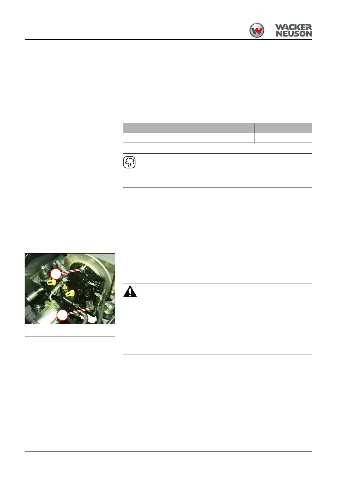
4. Remove the screw 12 and disconnect the plug.
5. Unscrew the union nuts and remove the hydraulic hoses.
6. Close the openings oil-tight with the plugs.
Injury hazard due to heavy component.
► Use lifting gear of sufficient lifting capacity.
► Use functionally safe lifting gear.
► Use the lifting gear on firm and level ground.
► Fasten the lifting gear in a suitable position of the component, or in a
position provided for this.
7. Fasten suitable lifting gear (for example, a round sling) onto the
variable displacement pump.
8. Tighten the lifting gear.
9. Remove the variable displacement pump from the clutch bell. To do
this, remove a screw 13 on the top and bottom sides.
Designation Weight
Variable displacement pump A4VG40DA 31 kg