SHB WL34 * 2.0 4-13
Travel drive 4
Variable displacement motor
Checking and adjusting the control initiation of the variable displacement motor
Adjust the control initiation in such a way that the variable displacement
motor switches to high capacity (“G” = “M1”) after reaching approximately
half of the high pressure of the variable displacement pump (“G” > 0.5 x
“M
A
”).
Checking
1. Release the pressure in the hydraulic system – see “Releasing
residual pressure in the hydraulic system” on page E-32.
2. Disassemble the cover panel of the foot well – see “Removing/
installing the footwell cover panel” on page 1-18.
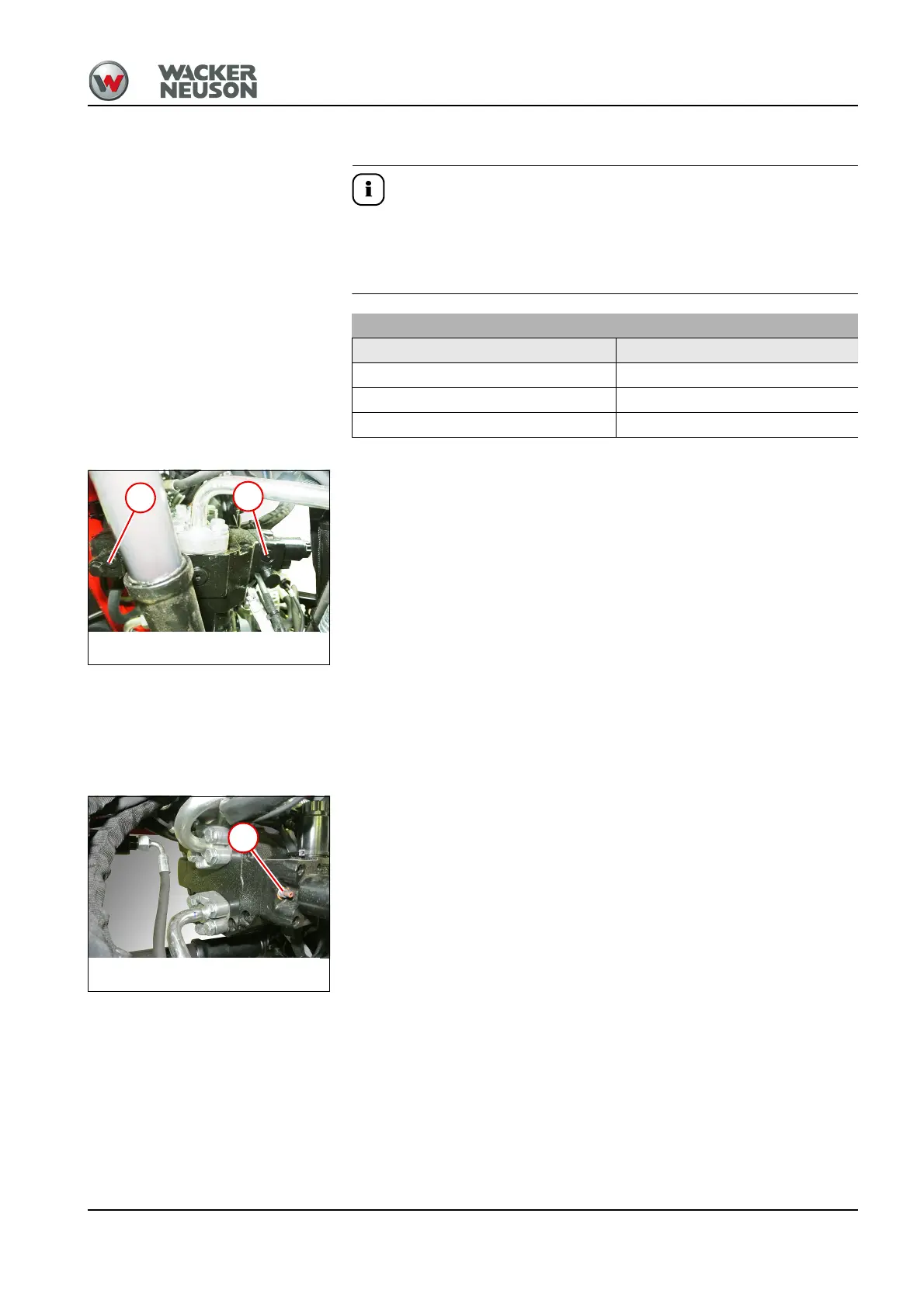
3. Unscrew two screws (4 and 5).
4. Screw in and tighten two test pressure gauges.
5. Connect one test pressure gage (0 ... 600 bar) to each measurement
connection.
6. Carefully drive the loader in front of an obstacle with the quickhitch.
7. Select the fast forward travel range.
8. Drive the loader against the obstacle and slowly increase the engine
speed to maximum.
9. Read pressure G and M
1
on the test gages.
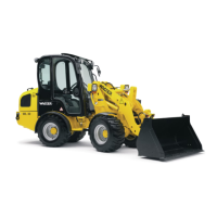
Adjustment
1. Loosen nut (6).
2. To adjust the control initiation with the screw:
➥ Turn the screw clockwise: earlier control initiation (at lower pressure
“G”).
➥ Turn the screw anticlockwise: later control initiation (at higher pressure
“G”).
3. Tighten the nut.
4. Check the control initiation.
Pressure (bar) at measuring point
G M
1
< 220 bar 0 bar
= 220 bar 110 bar
> 220 bar Same as G