Maintain the sample management system
July 29, 2013, 715003794 Rev. B 211
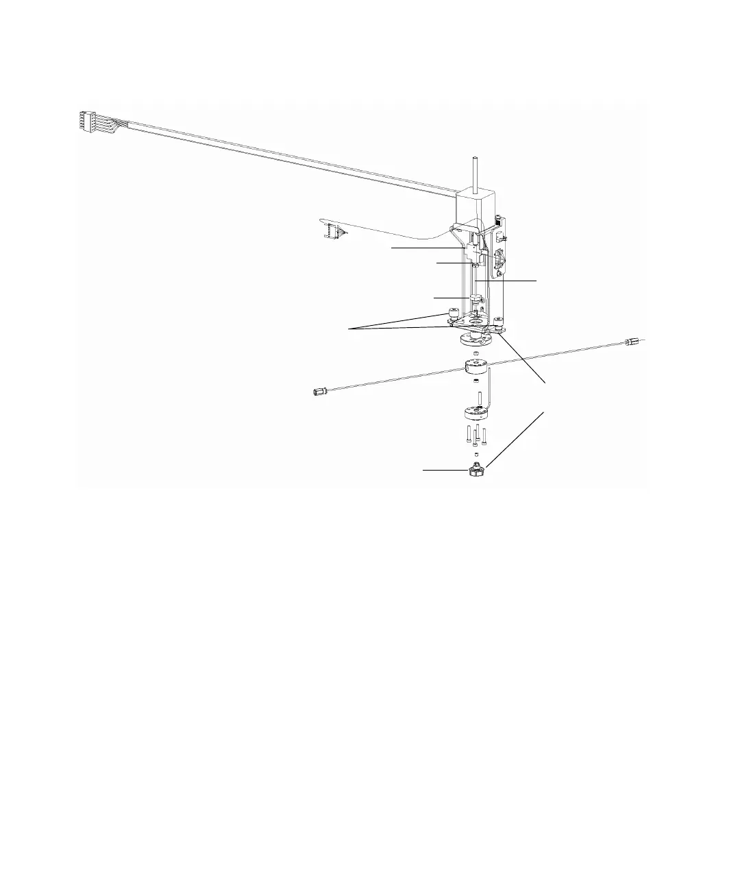
Injector assembly components:
To access the injector assembly:
Note: This procedure applies only to a separations module with no column
heater or column heater/cooler option installed. If the column heater or
column heater/cooler option is installed, see page 201 for instructions on how
to remove the side panel of the separations module.
1. Power-off the separations module, and disconnect it from the electrical
outlet.
2. Remove the 2 screws that secure the separations module’s right-hand
side panel.
3. Slide the side panel to the rear, off the rear panel posts, to access the
injector assembly.
Seal pack assembly
(exploded view)
Captive mounting
screws
Lower frit retainer
Upper frit retainer
Compression screw
Needle tee
Sensor
cable
Injector motor
cable
Needle