Signal connections
July 29, 2013, 715003794 Rev. B 71
I/O signal connections
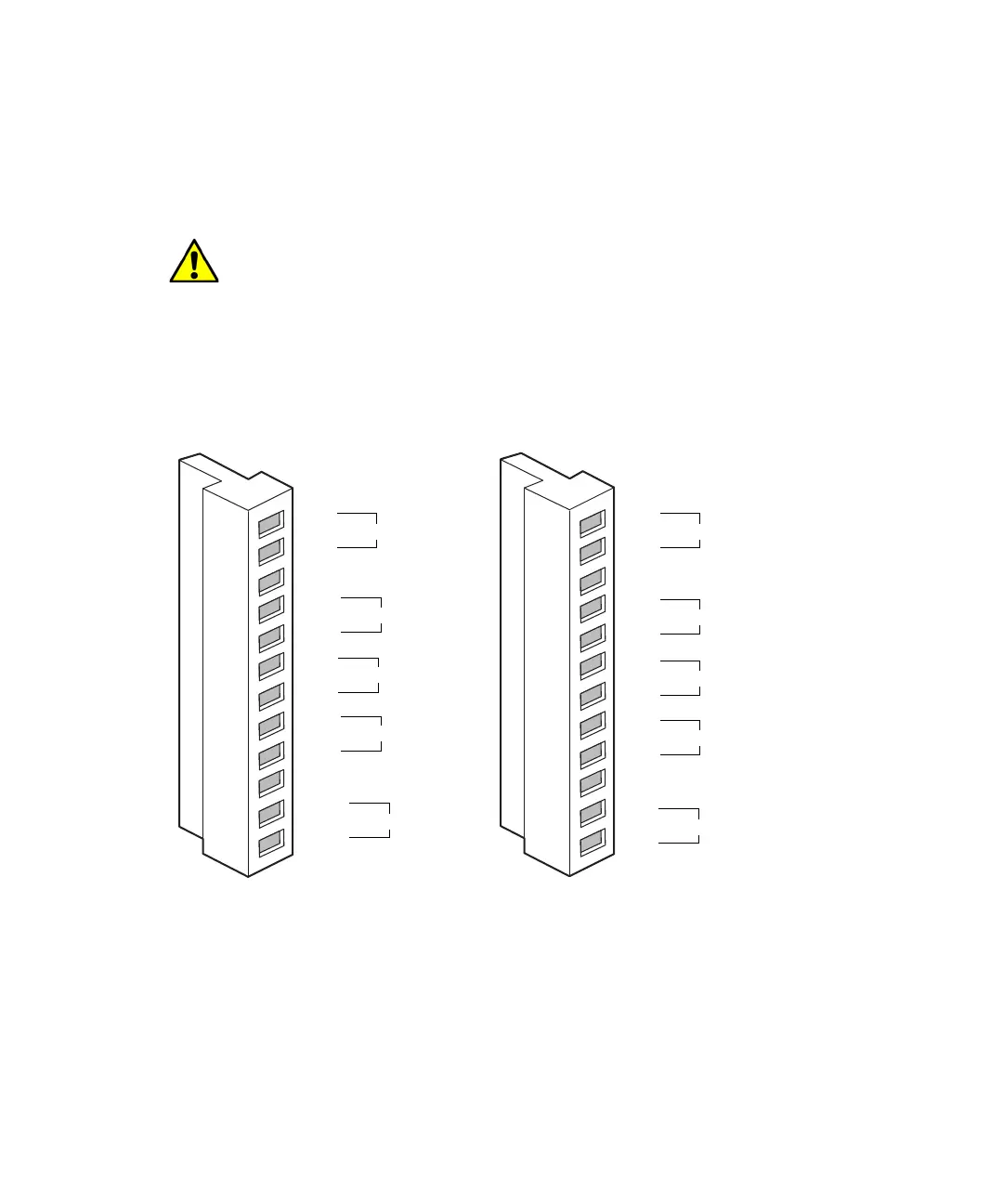
The rear panel includes two removable connectors that hold the screw
terminals for I/O signals. These connectors are keyed so that they can be
inserted only one way.
I/O signal connectors:
I/O signals
The following table describes the signals sent via the I/O connectors of the
separations module. See Appendix B for information about the electrical
specifications of each signal.
Caution: To avoid the risk of damaging other components, do not
remove the keys in the A and B connectors. These keys ensure that the
A connector fits only in the right-hand slot and the B connector only in
the left-hand slot (when you face the rear panel).
Connector A
Connector B
Inject Start
Stop Flow
Hold Inject 1
Hold Inject 2
Chart Out
Ground
Ground
Switch 1
Switch 2
Ground
Switch 3
Switch 4
Ground
Run Stopped
1
2
3
4+
5-
6+
7-
8+
9-
10
11
12
1
2
3
4
5
6
7
8
9
10
11
12