2 Install the e2695 Separations Module
62 July 29, 2013, 715003794 Rev. B
To install the needle-wash and plunger seal-wash reservoirs:
1. Place the needle-wash reservoir and plunger seal-wash reservoir in the
drip tray atop the separations module.
2. Place the needle-wash inlet line (green) in the needle wash reservoir.
3. Place the needle-wash outlet line (yellow or clear) and the sample loop
waste line (clear) in a suitable waste container.
4. Remove the diffuser from the plunger seal-wash inlet line (clear, labeled
Pump Wash In), insert the line through a reservoir cap, reinstall the
diffuser on the end of the line, and install the cap on the plunger
seal-wash reservoir.
5. Place the plunger seal-wash waste line (clear) in a suitable waste
container.
Connect the column
The red outlet tubing of the sample management system, which connects to
the column inlet, is located behind the right-hand side panel.
When you are connecting the separations module to a column switching valve,
connect the red outlet tubing to the column switching valve inlet. When you
are connecting the separations module to an external autosampler and
configuring for operating in Operate Gradient by Event In mode, connect the
red outlet tubing to the inlet of the autosampler.
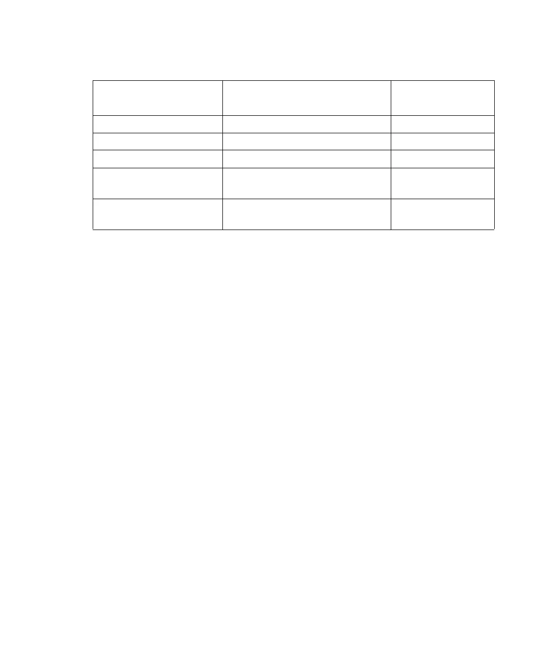
Needle wash and plunger seal wash line color code:
Wash line Color code
Inside diameter
(inches)
Needle-Wash Inlet Green 1/16
Needle-Wash Outlet Yellow or clear 1/16
Sample-Loop Waste Clear 1/16
Plunger Seal-Wash
Inlet
Clear (labeled “Pump Wash
In”)
1/8
Plunger Seal-Wash
Waste
Clear 1/8