List of Figures
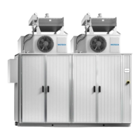
Figure 1: APS with 1-2 APUs ...................................................................................... 12
Figure 2: APS with 3-4 APUs ...................................................................................... 12
Figure 3: Product identification of APS series ............................................................. 12
Figure 4: Example of a type plate ................................................................................ 13
Figure 5: Example of an option plate ........................................................................... 14
Figure 6: Schematic structure (APS with 1-2 APUs) .................................................... 28
Figure 7: Schematic structure (APS with 3-4 APUs) .................................................... 29
Figure 8: Interior view front Seismic with protective cover ........................................... 33
Figure 9: Interior view back Seismic with protective cover ........................................... 33
Figure 10: Interior view control unit Seismic ................................................................ 33
Figure 11: Detail view stiffening strive ......................................................................... 33
Figure 12: Detail view mounting point ......................................................................... 33
Figure 13: Exterior view front ...................................................................................... 35
Figure 14: Exterior view back ...................................................................................... 35
Figure 15: Dimensioning dehumidifier outlet (bottom view) ......................................... 36
Figure 16: Interior view front with protective cover ...................................................... 37
Figure 17: Interior view back with protective cover ...................................................... 37
Figure 18: Interior view front ....................................................................................... 38
Figure 19: Harmonic filter (detail view of interior view front) ........................................ 39
Figure 20: Interior view back ....................................................................................... 40
Figure 21: Interior view control unit ............................................................................. 41
Figure 22: Packaging information – cooling tower ....................................................... 43
Figure 23: Cooling tower on the pallet ......................................................................... 44
Figure 24: APS with 1-2 APUs on the pallet ................................................................ 44
Figure 25: APS with 3-4 APUs on the pallet ................................................................ 44
Figure 26: Transport wooden box with pallet (dimensioned) (APS with 1-2 APUs) ...... 45
Figure 27: Transport wooden box with pallet (dimensioned) (APS with 3-4 APUs) ...... 45
Figure 28: Transport wooden box with pallet (dimensioned) (cooling tower) ............... 46
Figure 29: Centre of gravity symbol ............................................................................ 48
Figure 30: Centre of gravity (APS with 1-2 APUs) ....................................................... 48
Figure 31: Centre of gravity (APS with 3-4 APUs) ....................................................... 48
Figure 32: Transport with hoisting gear (APS with 1-2 APUs) ..................................... 49
Figure 33: Crane transport .......................................................................................... 50
Figure 34: Container Loading ...................................................................................... 51
Figure 35: Schematic view of the foundation ............................................................... 60