Figure 36: Exterior view front (APS with 1-2 APUs)..................................................... 61
Figure 37: Hole dimension of the APS carrier (APS with 1-2 APUs) ............................ 61
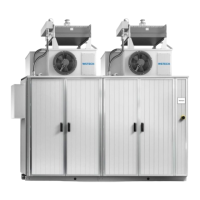
Figure 38: Exterior view front (APS with 3-4 APUs)..................................................... 62
Figure 39: Hole dimension of the APS carrier (APS with 3-4 APUs) ............................ 63
Figure 40: Height and length definition of APS ............................................................ 64
Figure 41: Centroid (geometric centre) (APS with 1-2 APUs) ...................................... 64
Figure 42: Centroid (geometric centre) (APS with 3-4 APUs) ...................................... 64
Figure 43: Centre of gravity (APS with 1-2 APUs and cooling tower) .......................... 65
Figure 44: Centre of gravity (APS with 3-4 APUs and cooling tower) .......................... 65
Figure 45: Cable entry areas (APS with 1-2 APUs) ..................................................... 66
Figure 46: Cable entry areas (APS with 3-4 APUs) ..................................................... 67
Figure 47: Cable entry areas (APS with 3-4 APUs and MV skid) ................................. 68
Figure 48: Example cable entries AC connection ........................................................ 69
Figure 49: Cable entry DC connection (bottom view) .................................................. 70
Figure 50: Safety area (APS with 1-2 APUs) ............................................................... 71
Figure 51: Safety area (APS with 3-4 APUs) ............................................................... 72
Figure 52: Safety area (APS with 3-4 APUs and MV skid) .......................................... 73
Figure 53: Door hinge (without protective cover) ......................................................... 74
Figure 54: Top of APS cabinet (without top cover) ...................................................... 74
Figure 55: Check door position ................................................................................... 75
Figure 56: Condition of door gaskets .......................................................................... 76
Figure 57: Check of screw connections....................................................................... 76
Figure 58: Door closing mechanism ............................................................................ 77
Figure 59: Door switch ................................................................................................ 78
Figure 60: Positioning door switch .............................................................................. 78
Figure 61: Service access to wet location (with cover) ................................................ 80
Figure 62: Service access to dry location (without cover) ............................................ 80
Figure 63: Cooling tower without top cover (top view) ................................................. 80
Figure 64: Positioning of cooling tower........................................................................ 81
Figure 65: Mounting the outer area of the cooling tower (detail view) .......................... 82
Figure 66: Mounting the inner area of the cooling tower (detail view) .......................... 82
Figure 67: Applying the cabinet sealing on the top cover ............................................ 83
Figure 68: Positioning the radial fan ............................................................................ 84
Figure 69: Mounting the radial fan ............................................................................... 84
Figure 70: Terminal strip (-X205.3) ............................................................................. 85
Figure 71: Connection of radial fans ........................................................................... 85
Figure 72: Connection of cooling tower ....................................................................... 86