ELECTRICAL COMPONENTS
8-191
▼▼▼▼ ▼ ▼▼▼▼▼▼▼▼▼ ▼ ▼▼▼▼ ▼ ▼▼▼▼ ▼ ▼▼▼▼▼▼▼
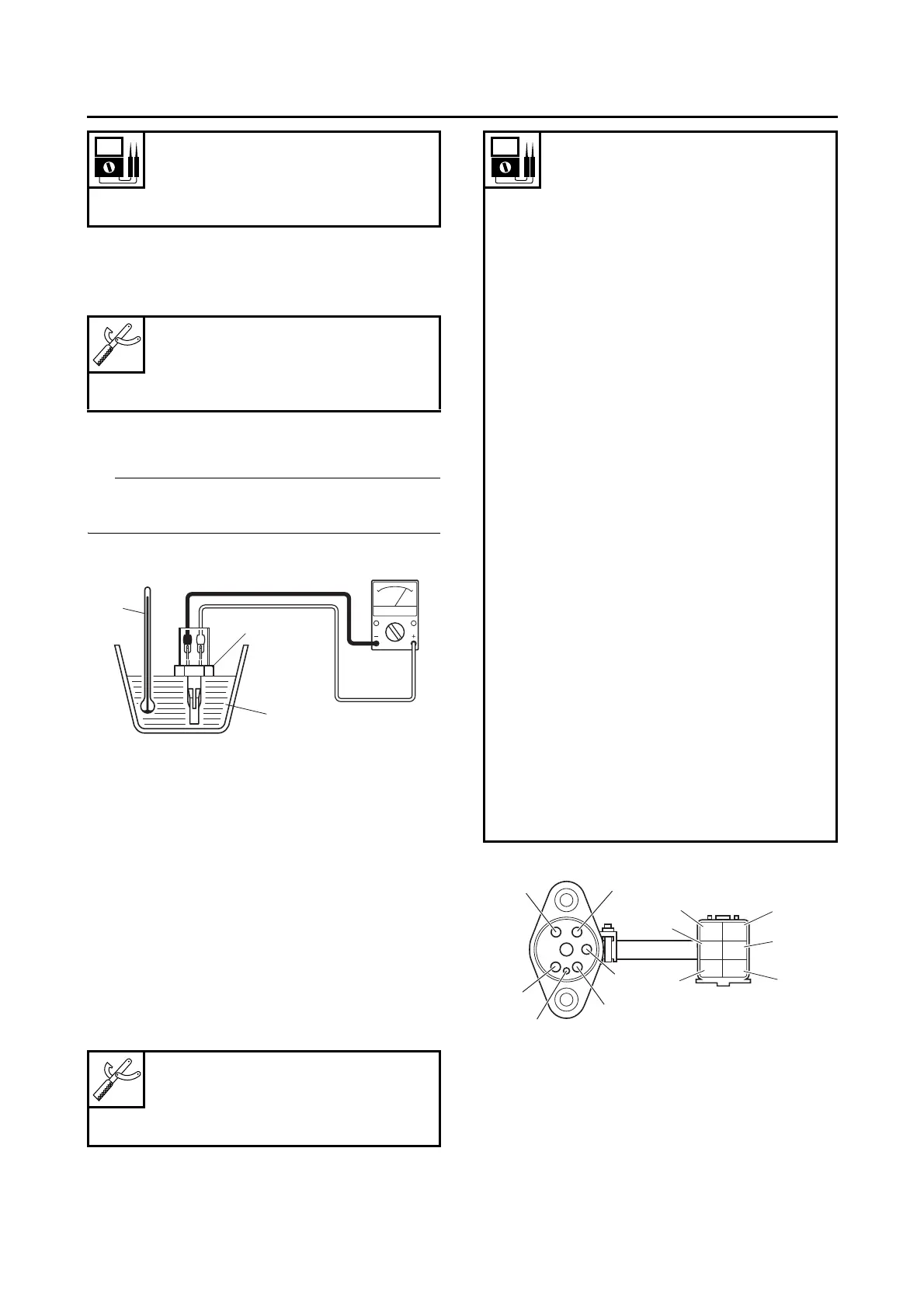
a. Connect the pocket tester (Ω × 100/× 1 kΩ) to
the air temperature sensor terminals as
shown.
b. Immerse the air temperature sensor “1” in a
container filled with water “2”.
Make sure that the air temperature sensor termi-
nals do not get wet.
c. Place a thermometer “3” in the water.
d. Heat the water or let it cool down to the spec-
ified temperatures.
e. Measure the air temperature sensor resis-
tance.
▲▲▲▲ ▲ ▲▲▲▲▲▲▲▲▲ ▲ ▲▲▲▲ ▲ ▲▲▲▲ ▲ ▲▲▲▲▲▲▲
EAS1MC1026
CHECKING THE GEAR POSITION SWITCH
1. Remove:
• Gear position switch
(from crankcase)
2. Check:
• Gear position switch
Out of specification → Replace the gear posi-
tion switch.
EAS1MC1027
CHECKING THE FUEL INJECTORS
1. Check:
• Fuel injector resistance
Out of specification → Replace the fuel injec-
tor.
Air temperature sensor resis-
tance
5.4–6.6 kΩ at 0 °C (32.0 °F)
290–390 Ω at 80.0 °C (176.0 °F)
Pocket tester
90890-03112
Analog pocket tester
YU-03112-C
Pocket tester
90890-03112
Analog pocket tester
YU-03112-C
Result
Neutral position
Continuity
Positive tester probe →
sky blue “1”
Negative tester probe →
Switch terminal “a”
1st position
Continuity
Positive tester probe →
black/yellow “2”
Negative tester probe →
Switch terminal “b”
2nd position
Continuity
Positive tester probe →
pink “3”
Negative tester probe →
Switch terminal “c”
3rd position
Continuity
Positive tester probe →
yellow/white “4”
Negative tester probe →
Switch terminal “d”
4th position
Continuity
Positive tester probe →
blue/white “5”
Negative tester probe →
Switch terminal “e”
5th position
Continuity
Positive tester probe →
black/red “6”
Negative tester probe →
Switch terminal “f”
P
Sb
Y/W
L/WB/R
B/Y
1
2
3
f
e
d
c
a
b
4
5
6