6-64
SHAFT DRIVE
CHAS
*****************************************************
NOTE:
Thrust washer
Thickness (mm) 1.2, 1.4, 1.6, 1.8, 2.0
*****************************************************
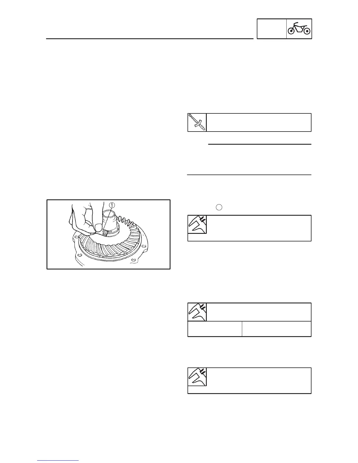
Ring gear thrust washer clearance mea-
surement steps:
D Remove the ring gear assembly.
D Place four pieces of Plastigauge
between
the originally installed ring gear thrust washer
and the ring gear.
D Install the ring gear assembly and tighten the
bolts to specification.
Bolt (bearing housing):
23 Nm (2.3 mSkg)
When using Plastigauge
to measure the ring
gear thrust washer clearance do not turn the
shaft drive and ring gear.
D Remove the ring gear assembly.
D Measure the ring gear thrust washer clear-
ance and the width of the flattened Plasti-
gauge
1
.
Ring gear thrust washer
clearance:
0.1 0.2 mm
D If the clearance is correct, install the ring gear
assembly.
D If out of specification, select the correct thrust
washer.
Ring gear thrust washer selection steps:
D Using the following chart select the suitable
thrust washer.
D Repeat the measurement steps until the ring
gear thrust washer clearance is within the
specified limits.
Ring gear thrust washer
clearance:
0.1 0.2 mm
 Loading...