7-15
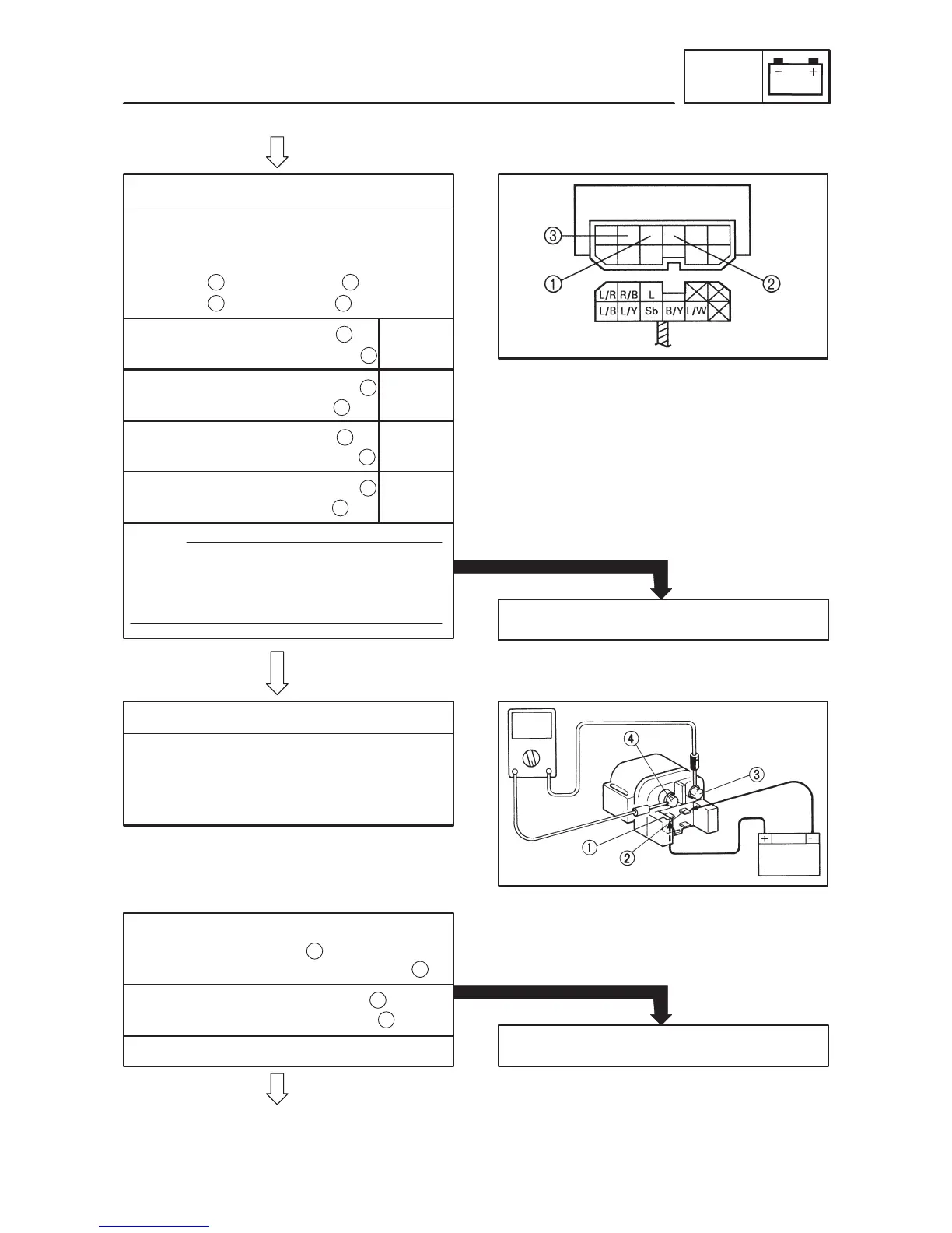
5. Relay unit (diode)
S Remove the relay unit from the wire har-
ness.
S Check for continuity as follows:
Sky blue – Black/Yellow
Sky blue – Blue/Yellow
:
EB803024
6. Starter relay
S Remove the starter relay from the wire har-
ness.
S Connect the pocket tester (Ω 1) and bat-
tery (12 V) to the starter relay terminals.
Tester (+) lead Sky blue
Tester (–) lead Black/Yellow
Replace the relay unit.
INCORRECT
Tester (+) lead Black/Yellow
Tester (–) lead Sky blue
NOTE:
When you switch the “–” and “+” leads of the
digital pocket tester the readings in the
above chart will be reversed.
CORRECT
Conti-
nuity
No Con-
tinuity
Tester (+) lead Sky blue
Tester (–) lead Blue/Yellow
Tester (+) lead Blue/Yellow
Tester (–) lead Sky blue
Conti-
nuity
No Con-
tinuity
Battery (+) terminal
Red/White terminal
Battery (–) terminal Blue terminal
S Check the starter relay for continuity.
Replace the starter relay.
NO CONTINUITY
Tester (+) lead Red terminal
Tester (–) lead Black terminal
1
1
2
3
CONTINUITY
:
1
2
2
1
1
3
3
1
1
2
3
4
ELECTRIC STARTING SYSTEM
ELEC
 Loading...