10.2 Encoder Orientation Constants
10-9
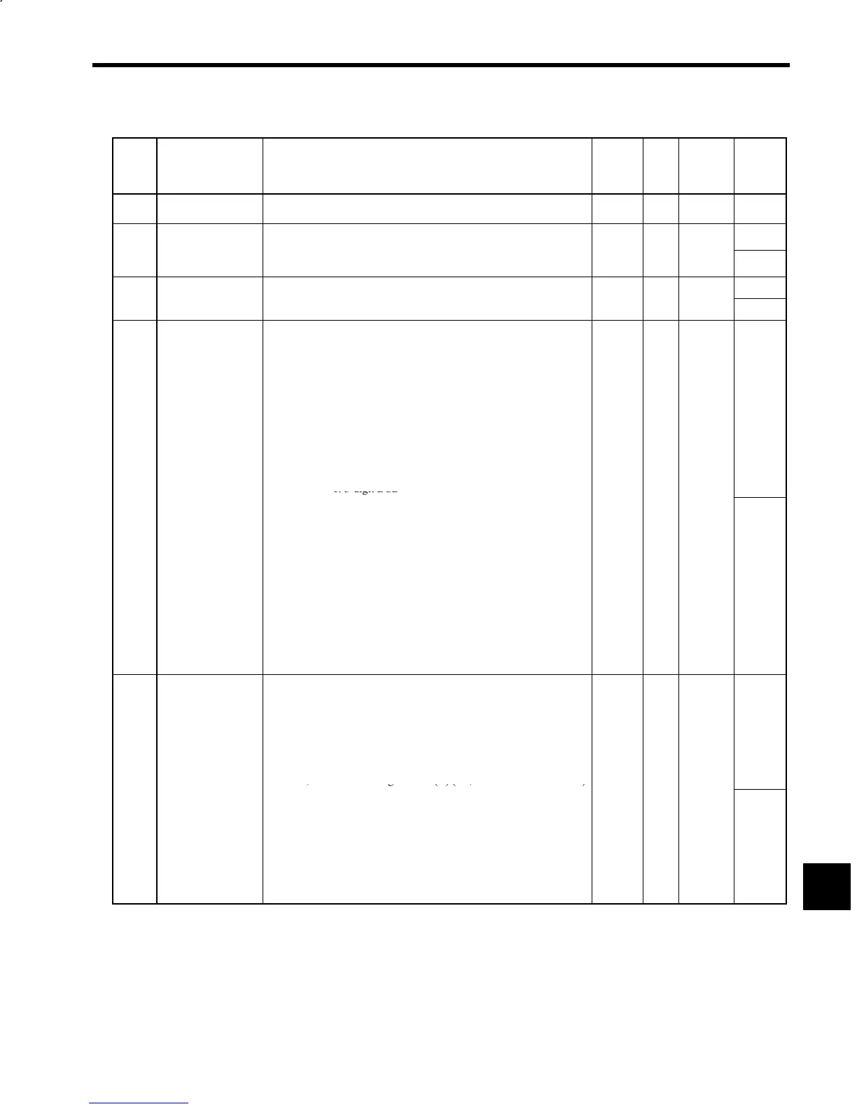
Table 10.2 Encoder Orientation Constants (continued)
Con-
stant
No.
Name Explanation Change
*
1
Unit Standard
Setting
Upper
Limit/
Lower
Limit
C2-16
Flux Level
φ
ORT
Flux level at completion of orientation. Motor noise and torque
changes in proportion to flux level.
No % 60 100
Orientation Speed
Reduction Coeffi-
Reduction coefficient to set orientation speed in proportion to the
travelin
an
le for incremental
ositionin
.
32767
C2-17
cient
K
SOR
.
No --- 0
0
C2-18
--- ---
---
to
C2-21
--- --- ---
---
Orientation Control
Signal Selections 1
SEL-E1
*2
Control mode setting signals, e.g., for specifying the direction of
rotation in orientation control.
S Bits 1 and 0: Positioning rotation direction
00: Automatically selected rotation direction
01: Same direction as the forward/reverse RUN signal
10: Fixed rotation direction
11: Automatically selected rotation direction
S Bit 2: Selection for fixed rotation direction
0: Forward rotation of load shaft
1: Reverse rotation of load shaft
S Bit 3: Stop position reference code
0: 12-bit binary
1: 3-digit BCD
---
C2-22
S Bit 4: Tuneup operation
0: Tuneup enabled
1: Tuneup disabled
S Bit 5: Incremental positioning reference point
0: Previous stop reference position
1: Current stop position
S Bit 6: Encoder selection
0: Load shaft encoder
1: Motor encoder
S Bit 7: Rotation direction of motor and load shaft
(automatically set at tuneup)
0: Reverse
1: Same
No --- 11000000
---
Orientation Control
Signal Selections 2
SEL-E2
*2
Dither signal pattern and gain
S Bit 0: DB selection upon orientation completion
0: Disabled
1: Stops by braking torque at orientation completion
S Bit 1: Dither signal pattern
0: 6 steps (83 Hz)
1: 2 steps (250 Hz)
S Bits 4, 3 and 2: Dither signal level (H) (i.e., MGR and LGR are OFF)
---
C2-23
000: 0.0% 011: 7.5%
110: 15.0% 001: 2.5%
100: 10.0% 111: 17.5%
010: 5.0% 101: 12.5%
S Bits 7, 6 and 5: Dither signal level (L) (i.e., MGR or LGR is ON)
000: 0% 011: 3%
110: 6% 001: 1%
100: 4% 111: 7%
010: 2% 101: 5%
No --- 00000000
---
10
 Loading...


