12.3 Inverter Faults
12 - 7
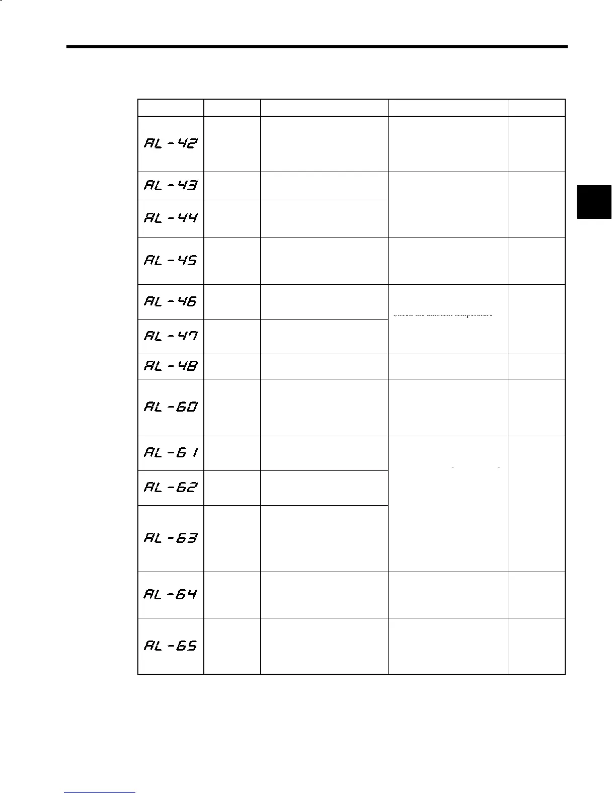
Table 12.2 Inverter Faults (continued)
Fault No. Name Contents Corrective Actions Error Code
Motor therm-
istor discon-
nection
Motor temperature detection therm-
istor was disconnected.
S Check the motor thermistor sig-
nal wiring.
S Check the motor ambient tem-
perature. (Raise the temperature
to above −10°C (14°F) or more.)
FfFF
Heatsink
overheat 1
Heatsink temperature exceeded up-
per limit (minor fault).
Heatsink
overheat 2
Heatsink temperature over upper
limit continued for one minute or
longer.
ec
t
eam
ent temperature
for effective cooling.
FfFF
Heatsink
thermistor
disconnection
Thermistor for heatsink temperature
detection was disconnected.
The ambient temperature is low
(−20°C(−4_F) or below).
S Replace the unit.
S Raise the ambient temperature
to above −20°C(−4°F).
FfFF
Control PCB
temperature
fault 1
Control PCB temperature exceeded
80°C (176°F) (minor fault).
Check the ambient temperature
Control PCB
temperature
fault 2
Control PCB temperature exceeded
85°C (185°F).
for effective cooling.
FfFF
Internal cool-
ing fan fault
Inverter internal cooling fan is
stopped.
Replace the internal cooling fan. FfFF
tuneup
incomplete
(Encoder
method
orientation)
Orientation command was input be-
fore tuning up (minor fault).
Perform orientation tuneup.
FffF
Phase-C sig-
nal detection
error
Phase-C signal could not be de-
tected during tuning up.
S Check the wiring of encoder sig-
Phase-C sig-
nal width er-
ror
Phase-C signal width exceeded 100
pulses.
nal lines.
S Confirm that encoder signal
lines are separated from main
circuit or other
ower lines.
Fault of num-
ber of pulses
per rotation
(Encoder
method
orientation)
Number of pulses per rotation ex-
ceeded 4096 ±1 during tuning up.
.
S Verify that motor and Inverter
are grounded.
S Replace the Orientation Card.
S Replace the encoder.
Position
detection sig-
nal cable
disconnection
Position detection encoder signal
cable was disconnected or con-
nected improperly.
S Check the wiring of load shaft
encoder signal lines.
S Replace the load shaft encoder.
S Replace the Orientation Card.
FffF
INC signal er-
ror
(Encoder
method
orientation)
INC signal input timing error
(minor fault)
After carrying out absolute posi-
tioning, change circuit to com-
mand INC signal.
FffF
12
 Loading...


