12.3 Inverter Faults
12 -11
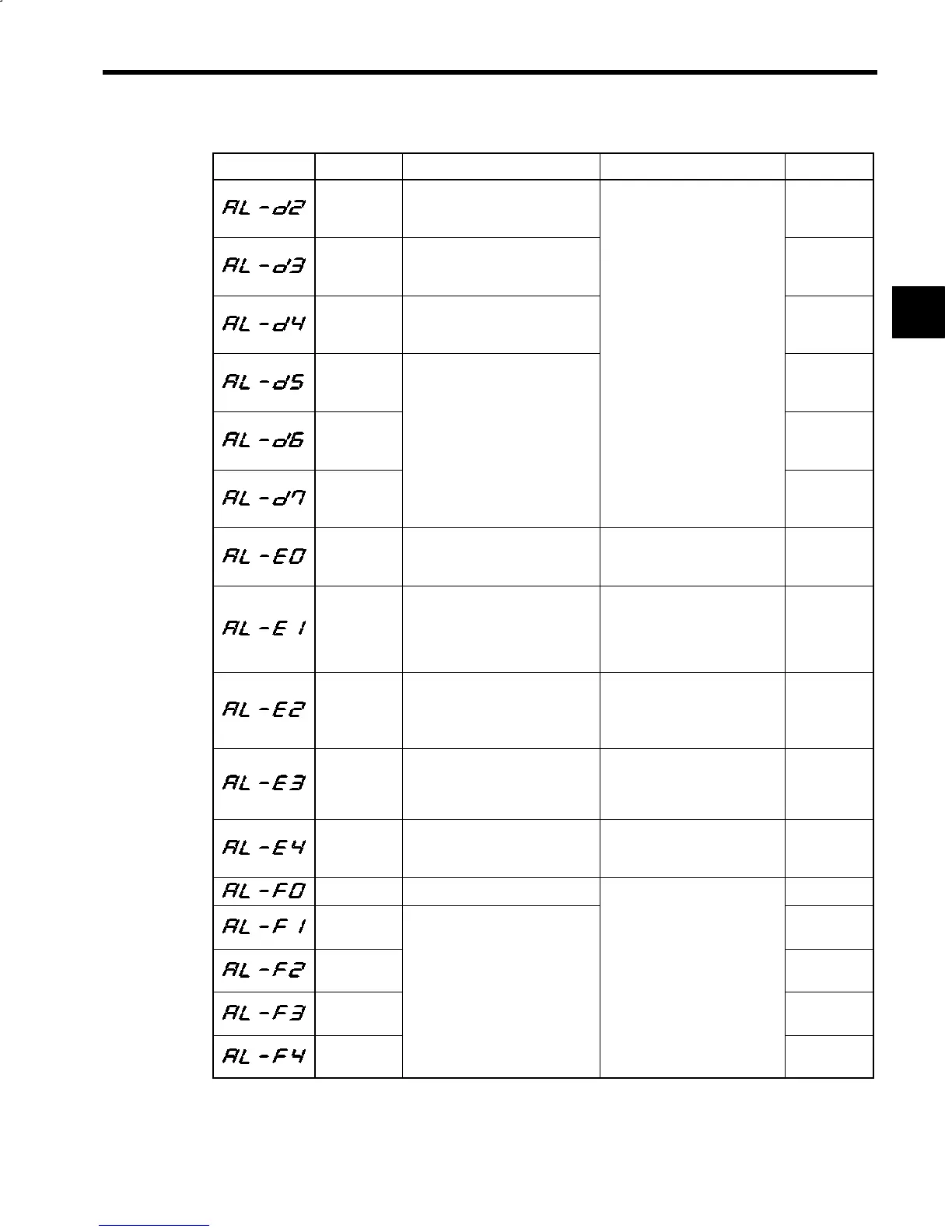
Table 12.2 Inverter Faults (continued)
Fault No. Name Contents Corrective Actions Error Code
CPU built-in
A/D Convert-
er error
CPU built-in A/D Converter error
ffFf
Phase U A/D
Converter er-
ror
Phase U current detection A/D Con-
verter error
ffFf
Phase W A/D
Converter er-
ror
Phase W current detection A/D
Converter error
ffFf
Control cir-
cuit I/O fault
1
Replace the control PCB.
ffFf
Control cir-
cuit I/O fault
2
Data transmission error between
CPUs.
ffFf
Control cir-
cuit I/O fault
3
ffFf
Motor code
selection error
Selected motor code (C1-25) does
not match Inverter capacity
(C1-56).
Check motor model, motor code
(C1-25), Inverter model, and In-
verter capacity selection (C1-56).
fffF
Motor code
unrecorded
Motor code set in C1-25 is not re-
corded.
S Check motor model and motor
code (C1-25).
S Check setting list for correct
PROM version of motor code
(C1-25).
fffF
Constant set-
ting range er-
ror
Memory (EEPROM) data exceeded
upper/lower limit.
S Confirm that rated speed
(C1-26) is within setting range.
S Check control constants.
S Replace the control PCB.
fffF
Orientation
Card mis-
match
Selected orientation bit does not
match Orientation Card.
S Check Orientation Card model
and orientation selection signal
(bit 0 of C1-39).
S Replace the Orientation Card.
fffF
Inverter ca-
pacity selec-
tion error
Selected Inverter capacity (C1-56)
does not match the Unit.
Check Inverter model and Invert-
er capacity selection (C1-56).
fffF
ROM error Memory (PROM) error
ffff
EEPROM er-
ror 1
ffff
EEPROM er-
ror 2
Replace the control PCB.
ffff
EEPROM er-
ror 3
Memory (EEPROM) error
ffff
EEPROM er-
ror 4
ffff
12
 Loading...


