12 -14
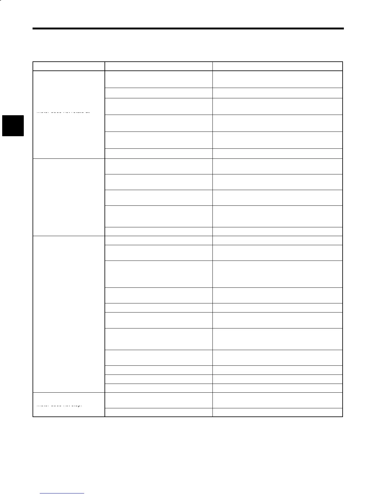
Table 12.3 Motor Faults and Corrective Actions (continued)
Fault Cause Corrective Action
Speed reference signal error
S Check speed reference on operating status display (U1-02).
S Readjust master speed reference function.
Incorrect setting of motor rated speed Check the setting of control constant C1-26.
Motor does not rotate at
Incorrect adjustment of motor speed *
Check the operating status display of the motor speed
(U1-01), and adjust the control constant (C1-12).
commanded speed.
Speed is controlled by P control.
Check if PPI signal is input or not on operating status display
(U1-09).
Torque limiting
Check whether external torque limit signals TLL or TLH is
input on operating status display (U1-09).
Control PCB fault Replace the control PCB.
Soft starter time setting error
(Set time is too long.)
Check the setting of control constant C1-10.
Motor code selection error
Check the setting of control constant C1-25 on the setting
list.
Extended acceleration/de-
celeration time
Torque limiting
Check whether external torque limit signals TLL or TLH is
input on operating status display (U1-09).
Excess load on load machine
S Check load status on the load factor meter for loss and inertia
moment of the load machine.
S Increase the capacity of Inverter and motor.
Control PCB fault Replace the control PCB.
Inverter output disconnection Check wiring between Inverter and motor.
Grounding error of motor or Inverter
Check continuity of motor and Inverter to see if they are
securely grounded.
Malfunction due to noise
(Poor encoder characteristics)
S Confirm that encoder signal lines are separated from Inverter
output wiring or other power lines.
S Check encoder cable specifications (whether the cable is a
shielded twisted-pair cable).
Control constant setting error
(especially speed control proportional gain)
Check control constants on the setting list.
Motor installation error Check for loose mounting bolts.
Heavy motor noise, vibration
Unbalanced motor
S Check if rotor is balanced.
S Replace the motor.
Motor fault
(Motor bearing fault, rotor fault)
S Run a motor alone to check if noise and vibration are within
specifications.
S Replace the motor.
Defective load machine coupling or centering
Confirm that coupling and centering are appropriate accord-
ing to the connection with load machine.
Insufficient strength of load machine Check the load machine for deformations or resonance.
Loose foundation bolts Check for loose foundation bolts on load machine.
Control PCB fault Replace the control PCB.
Motor does not stop.
Control signal does not operate.
Confirm that operation signal (FWD or REV) is open on
operating status display (U1-09).
Control PCB fault Replace the control PCB.
* Enabled for stand-alone drives (M5A) only.
12
Troubleshooting
 Loading...


