14.3 Options and Peripheral Units
14 -55
J
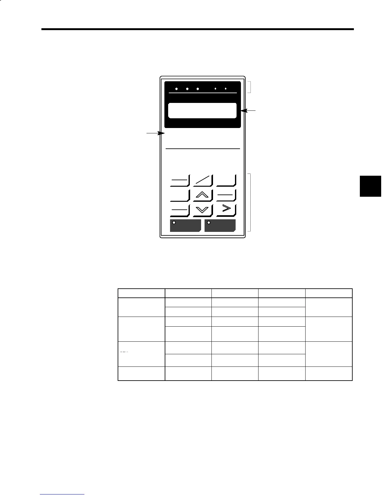
Digital Operator Appearance
The appearance of the Digital Operator is shown in the following diagram.
LOCAL
REMOTE
DIGITAL OPERATOR
JVOP-132
DSPL
DATA
ENTER
JOG
FWD
REV
RESET
RUN STOP
DRIVE FWD REV
REMOTE
REFSEQ
DRIVE
PRGM
JOG
DRIVE FWD REV REMOTE
REFSEQ
JVOP-132
Mode indicators
Display panel
Keypad (display
selection keys, etc.)
Fig 14.20 Digital Operator Display Panel and Operation Keys
J
Mounting the Digital Operator to the Panel
The following three methods can be used to mount the Digital Operator to a control panel. Mount the Digi-
tal Operator in accordance with the application.
Table 14.24 Mounting Method Features
Item Method 1 Method 2
*1
Method 3
*1
Remarks
Ease of mounting
Excellent Good Some difficulty
---
xtent o
pane
manipulation)
3 screw holes 3 screw holes 5 screw holes
Ease of removal
Some difficulty Some difficulty Excellent
Method 3 enables
emova
rom t
e
panel)
Fixed permanently Fixed permanently Can be mounted and
removed freely
t
eD
g
ta
Operator
to be mounted and
removed freely.
Applicable loca-
tion
Some difficulty Good Some difficulty
---
(Dusty locations,
etc.)
---
*2
---
Additional parts
code number
--- DACT32183-AD DACT32183-BD ---
* 1. Mounting methods 2 and 3 require additional parts such as metal plates or resin.
* 2. If mounting the Digital Operator in a dusty location or similar, mount packaging or another
buffer between the panel and the Digital Operator.
14
 Loading...


