15.3 Determining Drive Capacity
15 -13
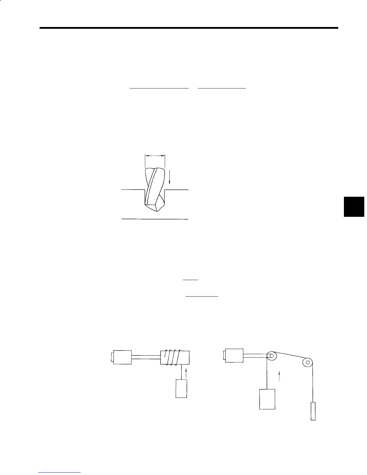
As shown in Fig. 15.16, when performing drill processing, the blade is mounted to the main axis and ro-
tated, opening a hole in the material being processed, so the motive force P
D
required can be expressed
using the following formula. The load torque M differs depending on the material, and the ratio of the drill
radius D: Feed speed f, so care must be applied.
P
D
=
M ⋅ 2πn
60 × 100 × 1000 × η
D
=
πD
2
f
4 × 1000 × S
D
η
D
(kW)
M: Drill load torque (N
⋅
cm)
n: Main axis speed (min
−1
)
η
D
: Machine efficiency 0.7 to 0.85
D: Drill radius (mm)
f: Feed speed (mm/min.)
S
D
: Cutting efficiency (i.e., cutting amount per 1 kW per minute) (CC/kW/min.)
D
f
Fig 15.16 Example of Drill Processing
J
Gravity Load Drive
The motive force required to move a load such as a crane or loader vertically differs greatly depending on
whether or not a counterweight is used. The motive force in each case can be expressed using the following
formulas.
Without counterweight
P
GL
=
m
L
V
6120η
(kW)
With counterweight
P
GLC
=
(
m
L
− m
C
)
V
6120η
(kW)
V: Vertical travel speed (m/min.)
η
: Machine efficiency
m
L
: Load mass (kg)
m
C
: Counterweight mass (kg)
Motor
Drum
Speed
V (m/min)
Load
m
L
(kg)
Motor
Speed
V (m/min)
m
L
(kg)
m
C
(a) Without Counterweight (b) With Counterweight
Fig 15.17 Gravity Loads
15
 Loading...


