Wiring
3.3.5 Wiring the Main Circuit
3 -22
D
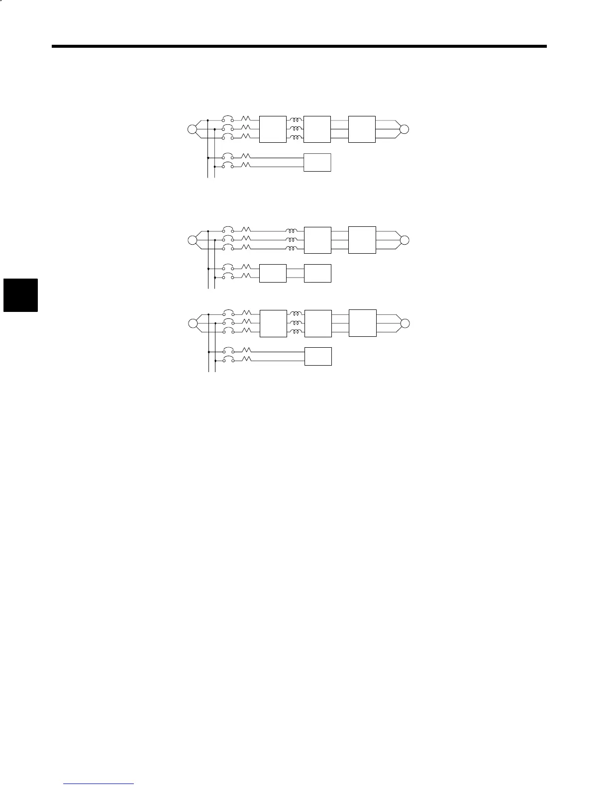
Example 1
MCCB
Use an exclusive noise filter
specified for inverters.
Power
Supply
MCCB
M
Other Control Device
~
Nois e
Filter
VS-
656MR5
VS-
626M5
Correct
Fig 3.13 Using Input Noise Filter
D
Example 2
~
MCCB
MCCB
M
VS-
656MR5
VS-
626M5
~
MCCB
MCCB
M
VS-
656MR5
VS-
626M5
Power
Supply
Other Control Device
General
Noise
Filter
Power
Supply
Other Control Device
General
Noise
Filter
Do not use general-purpose filters
because they are not effective.
Incorrect
Incorrect
Fig 3.14 Examples of Incorrect Noise Filter Installation
J
Wiring Precautions for Converter Control Power Supply Input
Make sure to connect MCCB with the converter control power supply input terminals A1/r and A2/t to
protect wiring.
J
Wiring Precautions for Main Circuit between Converter and Inverter
Connecting the Main Circuit DC Power Supply
Connect converter main circuit DC output terminals P/¨ and N/© to inverter main circuit power supply
input terminals P/¨ and N/© using exclusive-use connection bus bar. Secure bus bar using all the power
terminal screws and tighten to torque value of 4 to 5 N·m.
Connecting the Converter Control Power Supply Output
Connect converter control power supply output terminals P1 and N1 to inverter left-side control power
supply input terminals P1 and N1 using exclusive-use power cable.
J
Wiring Precautions for Inverter Main Circuit Output
Connecting the Inverter and Motor
Connect output terminals U/T1, V/T2 and W/T3 to motor lead wires U, V and W. Connection method is
indicated on the back of the terminal cover. Verify that the motor rotates in the forward direction (CCW:
counterclockwise when viewed from the motor load side) with the forward run command.
Strict Prohibition of Connecting Input Power Supply to Output Terminals
Do not connect power to the U/T1, V/T2, or W/T3 output terminals, or otherwise the internal inverter cir-
cuits will be damaged.
Strict Prohibition of Shorting or Grounding Output Terminals
Do not touch output terminals directly with your fingers or connect output lines to the Inverter’s case. Elec-
trical shock or a ground short may occur, creating an extremely dangerous situation. Never short the output
lines.
Strict Prohibition of Connection of Phase Advancing Capacitor or Noise Filter
Never connect a phase advancing capacitor or LC/RC noise filter to the output circuit, or otherwise the
Inverter may be destroyed or internal components damaged.
3
 Loading...


