4.3 Using a 12-bit Digital Speed Reference
4-11
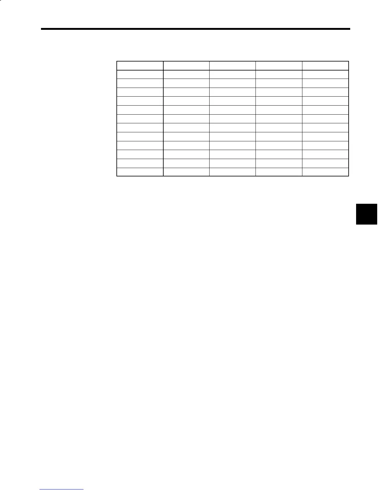
Digital Speed Settings
Signal 1CN Pin Number 12-bit Binary 3-digit BCD 2-digit BCD
D1
19 1 1 ---
D2
20 2 2 ---
D3
21 4 4 ---
D4
22 8 8 ---
D5
23 16 10 1
D6
24 32 20 2
D7
25 64 40 4
D8
26 128 80 8
D9
27 256 100 10
D10
28 512 200 20
D11
29 1024 400 40
D12
30 2048 800 80
D
All signals will be ON with the rated speed reference set in C1-26 if the 12-bit binary setting is selected.
D
If the 3- or 2-digit BCD setting is selected, a rated speed reference of 999 or 99 will be set in C1-26
respectively.
The input signal circuit for digital speed references is the same as the sequence input signal circuit explained
in 3.4.4 Sequence Input Signal Circuit (for Stand-alone Drive).
4