Control Signals
4.4.4 Details on Sequence Output Signals
4 -16
J
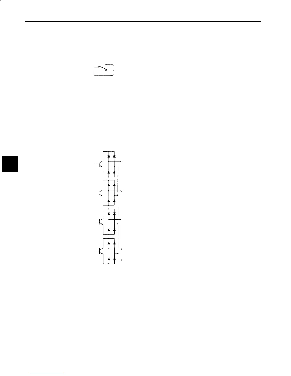
FLT (Fault Bit Signal)
Connector number: 6CN
Pin numbers:
43
44
45
D
The motor current will be shut off instantly when the protective circuit operates for overcurrent or over-
load protection and the motor will coast to a stop. The FLT signal will be output when the current is
shut off.
D
The FLT relay is of SPDT contact construction and operates together with the protective circuit.
D
Turn OFF the FWD, REV or ORT signal while the FLT signal is output and then display the fault at
the host system.
D
The fault number is displayed when the FLTL is output. Refer to the fault number.
D
For the relationship between the FLT and RST signals, refer to the RST signal in 4.1.4 Details on Se-
quence Input Signals.
J
FC0 to FC3 (Fault Code Signals 0 to 3)
Connector number: 6CN
Pin numbers:
26
27
28
30
29
D
A fault code signal is output to provide the details of the operation of the protective function.
D
Refer to tables 12.1 and 12.2 for the details of fault codes.
4