Chapter 3 PERFORMING MEASUREMENTS
3-69
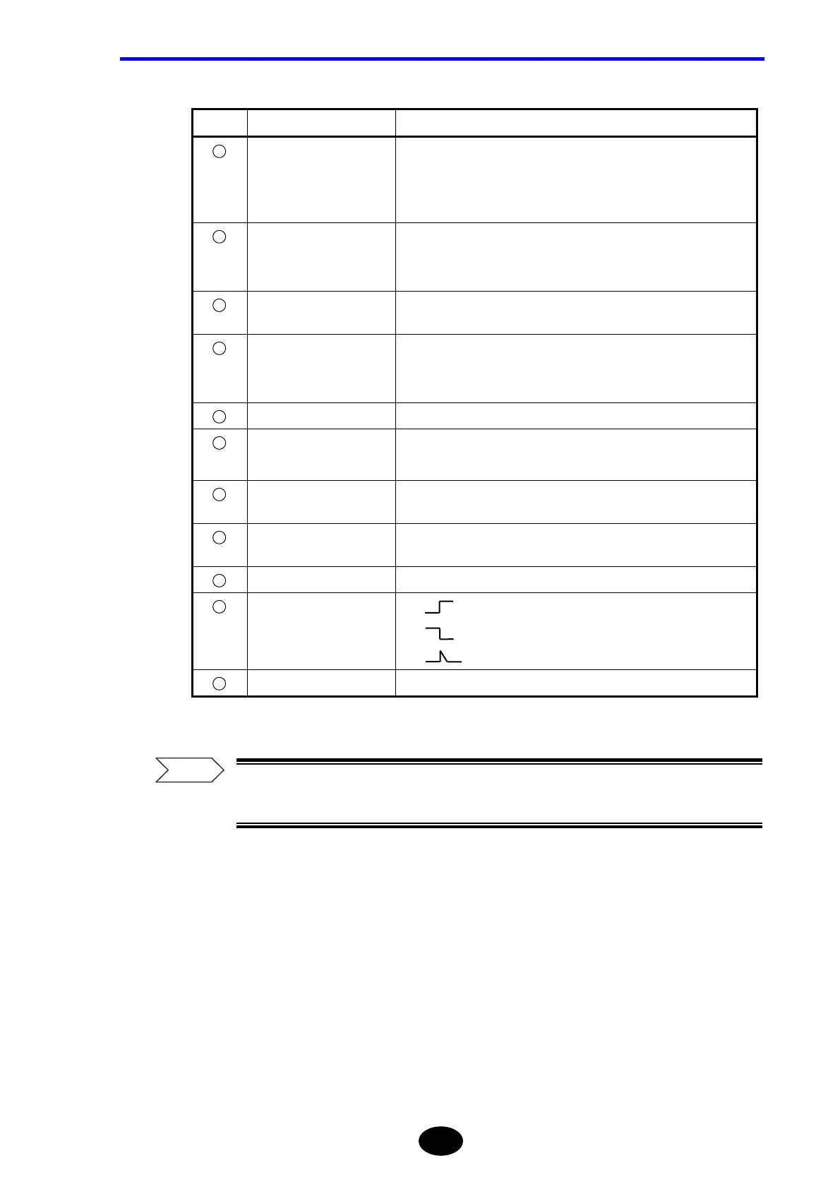
No. Name Description
1
TOTAL RL TOTAL RL Displays the return loss occurring between S and E
points.
If R point has been set, the return loss occurring between R and E
points will be displayed.
2
TOTAL LOSS Displays the total loss occurring between S and E points.
If R point has been set, the total loss occurring between R and E
points will be displayed.
3
FAULT EVENT Displays the number of events (fault events) whose splice loss or
return loss exceeds the preset threshold.
4
EVENT No. Displays event Nos. in ascending order, starting from the one
nearest to the left edge of the fiber cable.
“*” is displayed in front of fault event Nos.
5
DISTANCE (km) Displays the distance from the origin to the event.
6
SPLICE LOSS(dB) Displays the splice loss for the event.
It will be displayed in red if it exceeds the threshold
7
RETURN LOSS(dB) Displays the return loss for the event. It will be displayed in red if it
exceeds the threshold.
8
Cum LOSS(dB) Displays the loss accumulated, starting from the first event up to the
one you are currently referring to.
9
dB/km Displays the loss (per km) between events.
10
EVENT TYPE : Indicates that the event is a negative loss.
: Indicates that the event is a positive loss.
: Indicates that the event is reflection.
11
SECTION Gr INDEX Displays the group index between events.
For the method of setting the threshold for fault events, refer to page 5-36 and
5-37.
Refer
 Loading...


