Chapter 1 BEFORE USING THE INSTRUMENT
1-32
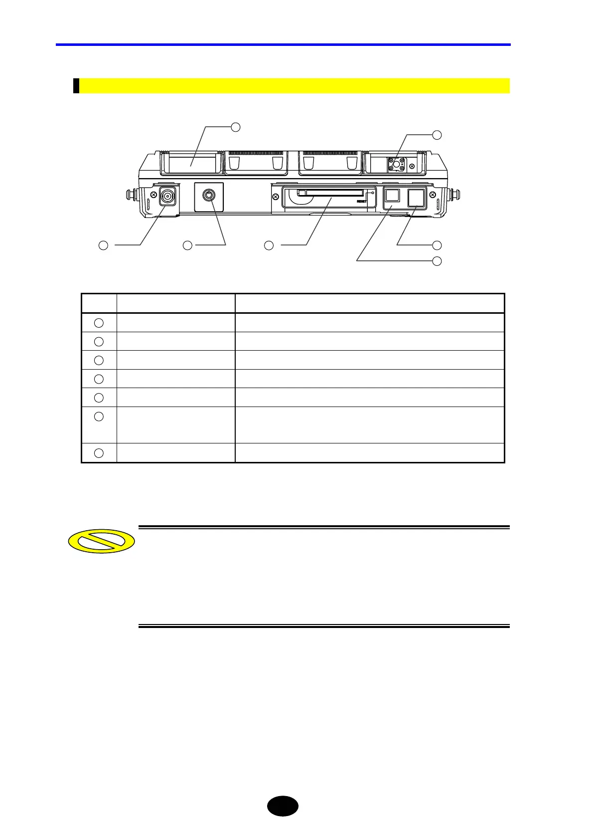
Top View
No. Name Description
1
Sub module port Used to connect an optional visible light source or optical power meter.
2
Optical adapter Used to connect the optical fiber to be measured.
3
DC power connector Used to connect the AC adapter.
4
Power switch Used to turn ON/OFF the power to the instrument.
5
PCMCIA slot Used to insert an optional IC card etc.
6
USB connector (host side)
2 ports
Used to connect FDD or memory.
7
USB connector (function side) Used to connect a personal computer.
•Two USB ports (host side) are available, but do not connect a storage medium or
printer to both ports.
•Now, sub modules are not available. It will be developed.
•It does not support USB connector (function side) yet.
1
2
3
4
5
6
7
Caution
 Loading...


