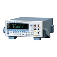
Two-terminal connection
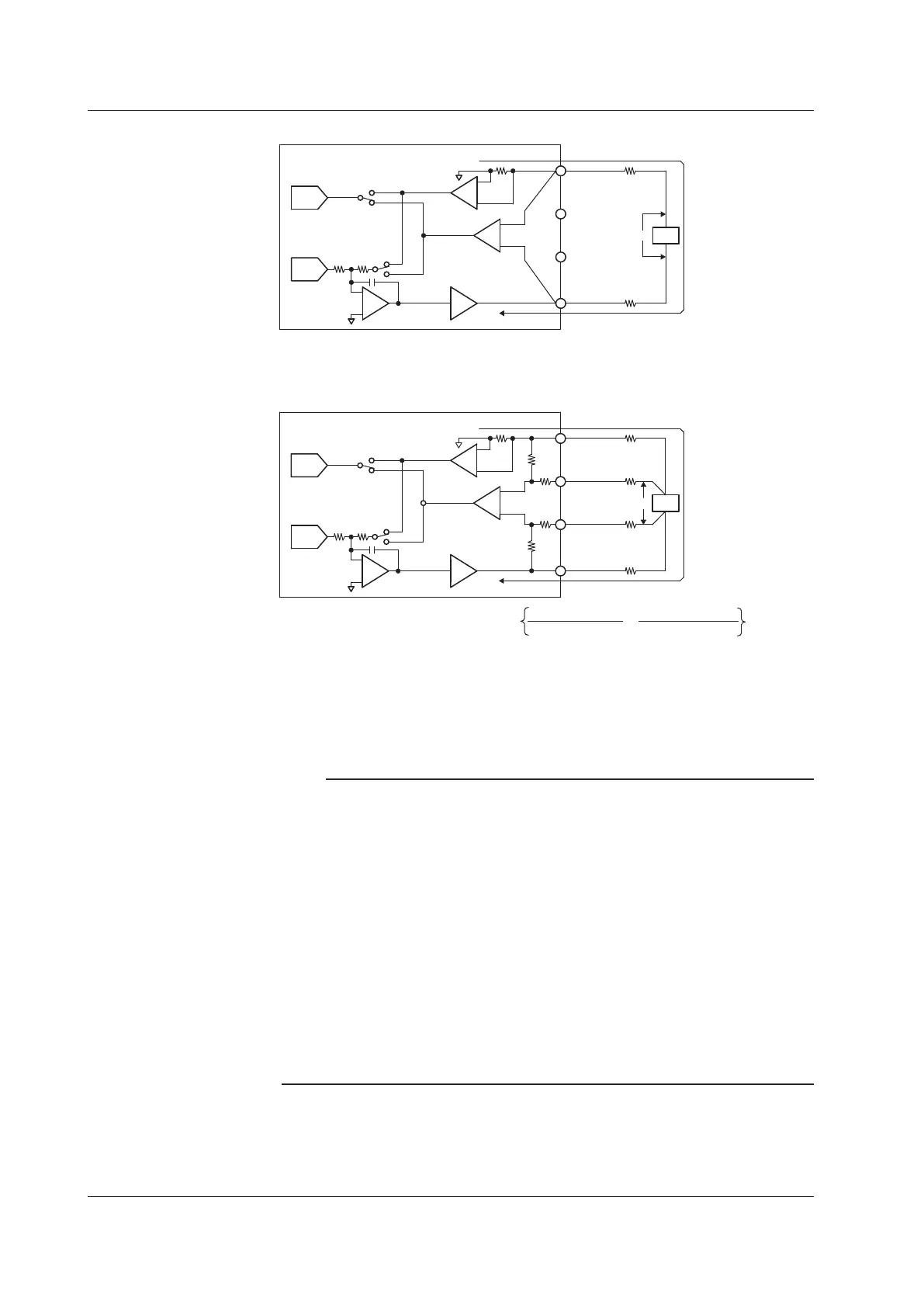
Four-terminal connection
GS200
ADC
Source
DAC
R1 R2
Power Amp
Vsns
Current
Sense
Rs
Voltage
Sense
OUTPUT Hi
SENSE Hi
SENSE Lo
OUTPUT Lo
r2
r1
DUT
Vd Id
-
+
-
+
-
+
ADC
Source
DAC
R1 R2
Power Amp
Vsns
Current
Sense
Rs
22
22
Voltage
Sense
OUTPUT Hi
SENSE Hi
SENSE Lo
OUTPUT Lo
r2
r1
DUTVd Id
-
+
-
+
-
+
r3
r4
GS200
1 MΩ
1 MΩ
r1 to r4: Lead wire resistance
Id: Current flowing through the DUT
Vd: Voltage applied to the DUT
Vsns: Voltage sensed by the GS200
(= voltage source level and measured current value)
A difference of Id × (r1 + r2) appears across Vd and Vsns.
This difference cannot be ignored if Id is large even if r1
and r2 are small.
A difference of
appears across Vd and Vsns, but this difference can be ignored
if r1 to r4 are small.
Id ×
+
r1 . (r3 + 22 Ω)
1 MΩ + r3 + 22 Ω + r1
r2 . (r4 + 22 Ω)
1 MΩ + r4 + 22 Ω + r2
Note
• If 4W (four-terminal connection) is used, the source voltage across the OUTPUT Hi and
OUTPUT Lo terminals will be larger than the voltage generated on the load. If the voltage
across the OUTPUT-SENSE terminals exceeds 0.5 V, the GS200 will not be able to
generate the voltage correctly, and abnormal load detection may be activated and cause the
output to turn off. Be sure that the voltage across the OUTPUT-SENSE terminals does not
exceed 0.5 V.
• The four-terminal connection does not function for the 10 mV and 100 mV ranges in voltage
source mode. You must use the two-terminal connection instead. Because the output
resistance is approximately 2
Ω
for these voltage ranges, they are not suitable when the
GS200 is connected to a load that allows current to flow (a low-impedance load). Connect a
high-impedance load, a load that is sufficiently larger than the output resistance.
•
T
o prevent oscillations due to stray capacitance and lead inductance, use twisted-pair lead
wires to connect to the OUTPUT Hi and OUTPUT Lo terminals. Likewise, use twisted-pair
lead wires to connect to the SENSE Hi and SENSE Lo terminals. In particular, wire the
lead wires short in the case of a high-capacity load in a four-terminal connection in voltage
source mode.
<<Corresponding Command Mnemonic>>
:SENSe:REMote 1|0|ON|OFF
4.2 Selecting the Wiring System (Remote Sense or Local Sense)
 Loading...