11-8
IM 05P02D41-01EN
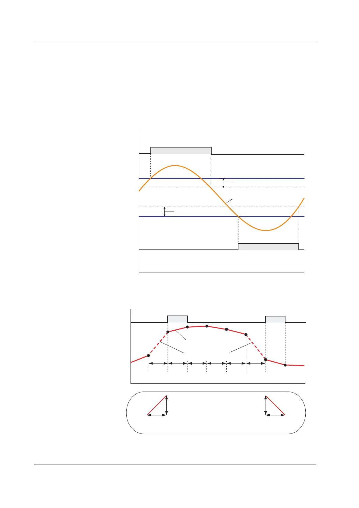
FeedbackInputHighLimitAlarmandFeedbackInputLowLimitAlarm
These alarms can be used only for Position proportional type..
These alarms monitor the feedback input (resistance or current) value.
The setting range for these alarms is 0.0 to 100.0%.
However, the setting range varies depending on whether the feedback input is a current
value(4to20mA)orresistancevalue(100Ωto2.5kΩ).
Current value: 4 mA corresponds to 0.0%, and 20 mA to 100.0%.
Resistancevalue(e.g.,1kΩ):Theresistancevaluewhenthevalveisfullyclosedafter
thevalvepositionadjustmentcorrespondsto0.0%,andtheresistancevaluewhenthe
valveisfullyopenedcorrespondsto100.0%.0Ωdoesnotcorrespondto0.0%,and1
kΩdoesnotcorrespondto100.0%.
Feedback input
ON OFF
ON
Contact type in the figure above: Energized when an event occurs (factory default).
Alarm hysteresis
Alarm hysteresis
OFF
high limit
alarm setpoint
low limit
alarm setpoint
high limit
alarm output
low limit
alarm output
PVVelocityAlarm
PV
VT VT VT VT VT VT
PV velocity
An alarm occurs if the velocity
exceeds this inclination.
OFF OFF OFFON ON
Velocity alarm
time setpoint
VT1 to VT2
Velocity alarm
setpoint
Velocity alarm
setpoint
Velocity alarm
time setpoint
VT1 to VT2
Exceeds the velocity
Contact type in the figure above: Energized when an event occurs (factory default).
Monitors the variation of the measured value for 2 points by the time
interval set in VT.
The PV velocity alarm function does not work the alarm hysteresis, the stand-by action
and the alarm delay timer functions.
11.1SettingAlarmType

 Loading...


