17-7
IM 05P02D41-01EN
Installation and Wiring
17
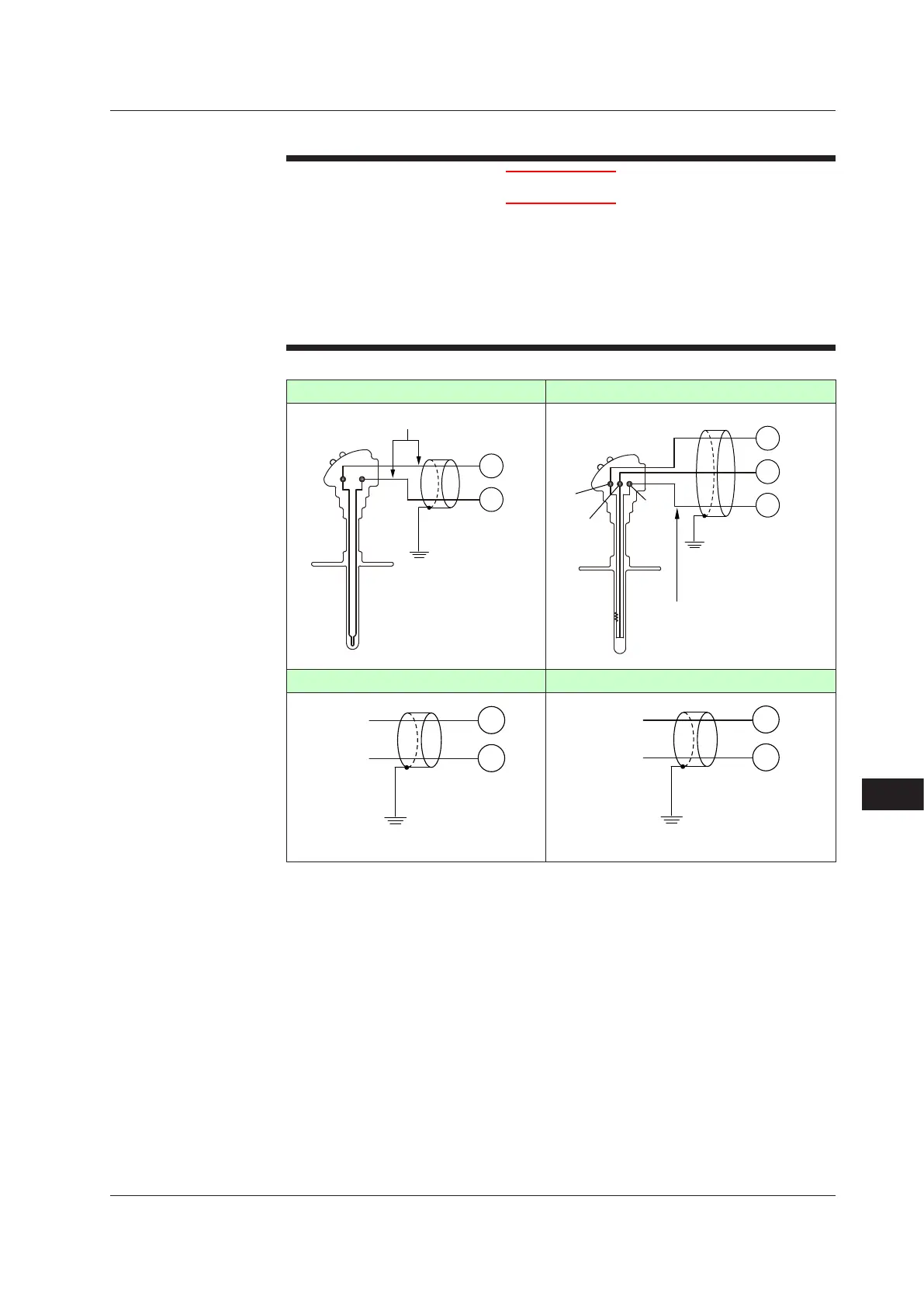
17.4.2 PV Input Wiring
CAUTION
1) Be careful of polarity when wiring inputs. Reversed polarity can damage the UP.
2) Keep the PV input signal line as far away as possible from the power supply
circuit and ground circuit.
3) For TC input, use shielded compensating lead wires for wiring. For RTD input,
use shielded wires that have low conductor resistance and cause no significant
differences in resistance between the three wires.
4) If there is a risk of external lightning surges, use a lightning arrester etc.
TC Input RTDInput(3-wiresystem)
203
202
TC
–
+
Grounding
Shield
203
202
201
RTD
A
B
b
Lead wire resistance per wire of
10 Ω or less. Make the resistance
of the three wires equal.
b
B
Grounding
PV
DCVoltage(mV,V)Input DC Current (mA) Input
203
202
–
+
–
Shield
204
203
+
+
–
Shield
Use
PV input is used for PV input.
17.4 Wiring

 Loading...


