1-13
IM 05P02D41-01EN
Introduction to Functions
1
1.8 DefinitionofMainSymbolsandTerms
MainSymbol
PV: Measured input value
SP: Target setpoint
OUT: Control output value
PRG, PROGRAM: Start of Program operation
RST, RESET: Stop of Program operation
LOC, LOCAL: Start of Local operation
HLD, HOLD: Pause of program operation
ADV, ADVANCE: Advance of segment
A/M: AUTO/MAN
AUTO: Automatic
MAN: Manual
E1, E3, and E4: Terminal areas
► 17.4Wiring
Engineering Units
Input range (scale): the PV range low limit is set to 0%, and the high limit is set to 100%
for conversion.
Input range (scale) span: the PV range span is set to 100% for conversion.
In this manual, the parameter setting range is described as the “input range” and “input
range span.” This means that engineering units are required to be set. Set a temperature
for temperature input.
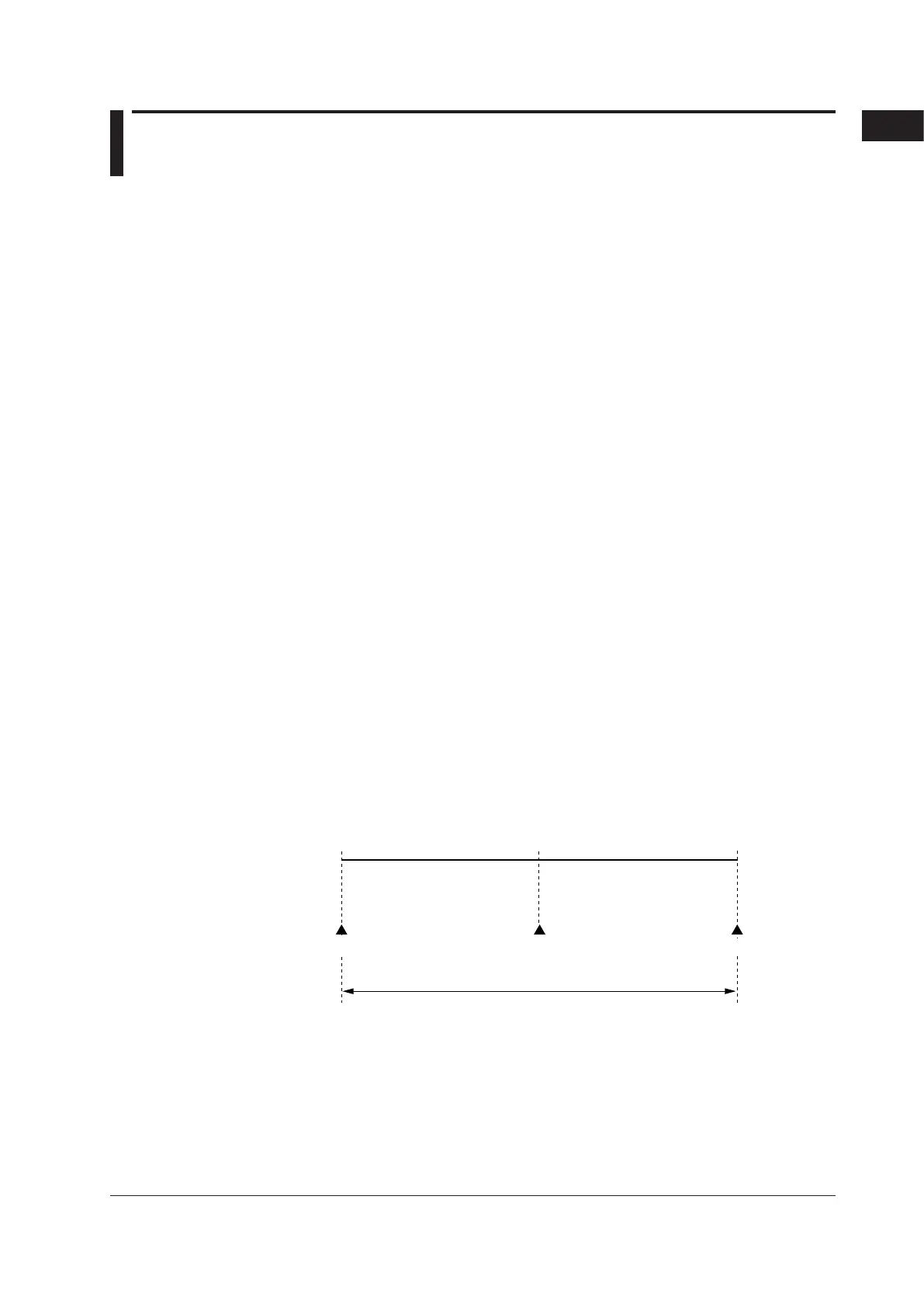
The following describes a conversion example.
When the PV input range is 100 to 600°C, 0% of the PV range is equivalent to 100°C,
50% of the PV range is equivalent to 350°C, and 100% of the PV range is equivalent to
600°C.
100% of the PV range span is equivalent to 500°C.
20% of the PV range span is equivalent to 100°C.
Minimum value of PV input range Maximum value of PV input range
100°C 600°C350°C
50% of PV input range
100% of PV input range span = 500°C
0% of PV input range 100% of PV input range
The above applies to the scale for voltage and current input.

 Loading...


