17-17
IM 05P02D41-01EN
Installation and Wiring
17
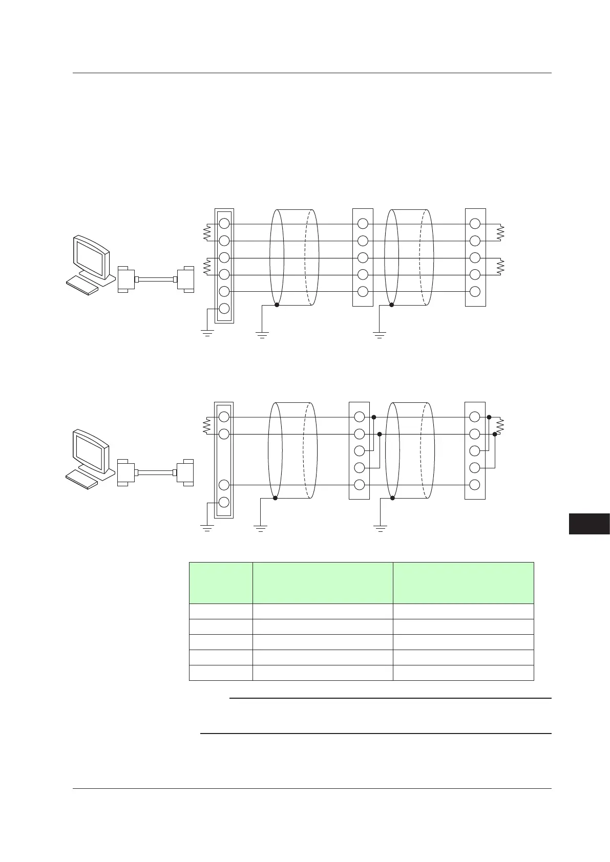
17.4.11 RS-485CommunicationInterfaceWiring
Wire as follows for Modbus communication, PC link communication, or ladder
communication.
Always connect a terminating resistor to the station at the end of the communication line.
► Detailsofcommunicationparametersettingsandcommunicationfunctions:UTAdvancedSeries
Communication Interface (RS-485, Ethernet) User's Manual
4-wireWiring
ML2-
SG
SDB (+)
SDA (–)
RDB (+)
RDA (–)
RDB (+)
RDA (–)
SDB (+)
SDA (–)
SG
RDB (+)
RDA (–)
SDB (+)
SDA (–)
SG
RS-232C
Straight cable
UP
2
1
4
3
5
6
UP
Grounding Grounding Grounding
Communication
cable
Communication
cable
PC
(External)
Terminating resistor
220 Ω 1/4 W
(External)
resistor
220 Ω 1/4 W
(External)
resistor
220 Ω 1/4 W
2-wireWiringof4-wireTerminal
SG
ML2-
UP
B (+)
A (–)
SDB (+)
SDA (–)
RDB (+)
RDA (–)
SG
SDB (+)
SDA (–)
RDB (+)
RDA (–)
SG
RS-232C
Straight cable
PC
4
3
5
6
Grounding Grounding Grounding
UP
(External)
Terminating resistor
220 Ω 1/4 W
(External)
resistor
220 Ω 1/4 W
Communication
cable
Communication
cable
Terminal
symbolabove.
(ForStandardmodel)UP35ASufx
code:Type3=
“1”
(For Detailed model) UP35A
Optionalsufxcode:/CH3
(ForStandardmodel)UP32ASufx
code:Type2=
“1”
RDB (+) 410 304
RDA (–) 411 305
SDB (+) 407 301
SDA (–) 408 302
SG 409 303
Note
ML2-x indicates a converter of YOKOGAWA. Other than this, RS232C/RS485 converters
can also be used. If another converter is to be used, check the electrical specifications of the
converter before using it.
17.4 Wiring

 Loading...


