17-15
IM 05P02D41-01EN
Installation and Wiring
17
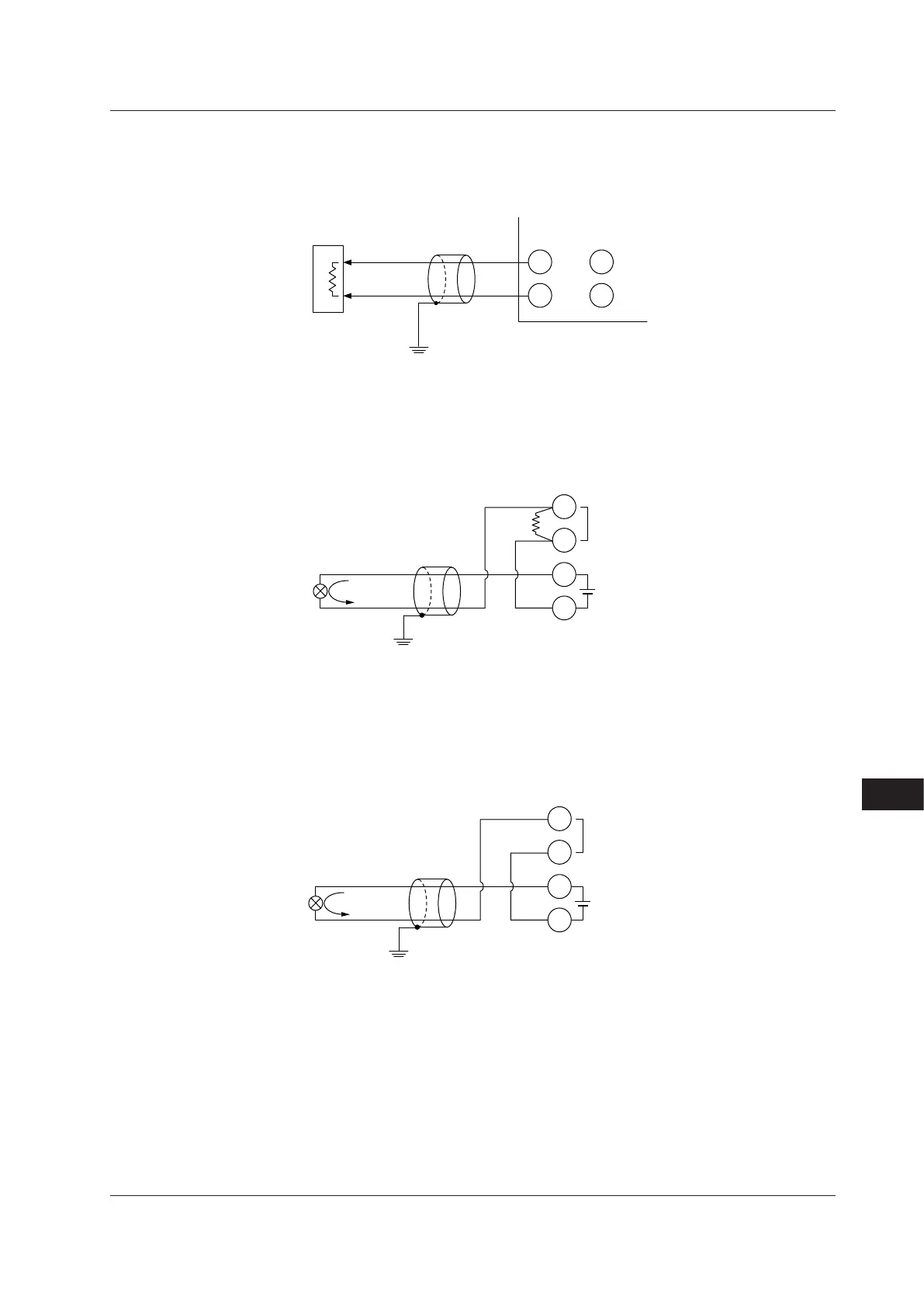
17.4.7 Retransmission Output Wiring
When retransmission output is not used for retransmission output, it can be used for 15 V
DC loop power supply.
The current output range can be changed.
206
205
208
207
Grounding
OUT
terminals
RET
terminals
Shield
–
+
Receiver
(Recorder etc.)
Receiving resistor:
600 Ω or less
17.4.8 15VDCLoopPowerSupplyWiring
This can be used when it is not used for retransmission output.
The controller is equipped with a non-isolated loop power supply (14.5 to 18.0 V DC) for
connecting a 2-wire transmitter.
PV input
0.4-2 V DC
Shield
–
RET terminals
100 Ω
206
205
203
202
4-20 mA DC
OUT terminal also can be used.
17.4.9 24VDCLoopPowerSupplyWiring(forDetailedmodel)
This can be used when the optional suffix code /L4 is specified.
The controller with the optional suffix code above is equipped with an isolated loop power
supply (21.6 to 28.0 V DC) for connecting a 2-wire transmitter.
PV input
4-20 mA DC
Shield
–
LPS terminals
506
505
203
204
4-20 mA DC
17.4 Wiring

 Loading...


