11-13
IM 05P02D41-01EN
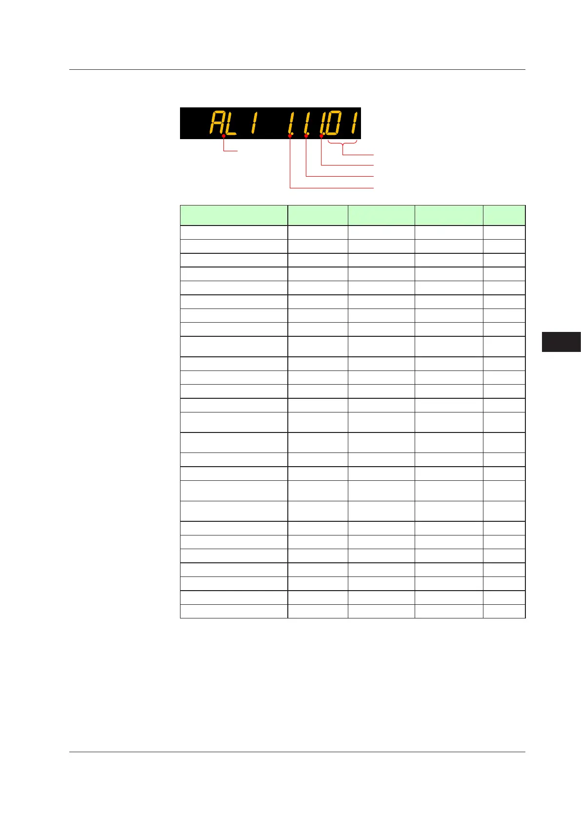
Alarm Functions
11
The following shows the example of setting PV high limit (01), With stand-by action (1),
De-energized(1),andLatch1action(1).
Alarm type
Symbol
Stand-by action
Energized/de-energized
Latch
Name
Latch action
(Note 1)
Energized (0) /
de-energized (1)
Stand-byaction
Without(0)/with(1)
Alarm
type
Disable 0 / 1 / 2 / 3 / 4 0 / 1 0 / 1 00
PV high limit 0 / 1 / 2 / 3 / 4 0 / 1 0 / 1 01
PV low limit 0 / 1 / 2 / 3 / 4 0 / 1 0 / 1 02
SP high limit 0 / 1 / 2 / 3 / 4 0 / 1 0 / 1 03
SP low limit 0 / 1 / 2 / 3 / 4 0 / 1 0 / 1 04
Deviation high limit 0 / 1 / 2 / 3 / 4 0 / 1 0 / 1 05
Deviation low limit 0 / 1 / 2 / 3 / 4 0 / 1 0 / 1 06
Deviation high and low limits 0 / 1 / 2 / 3 / 4 0 / 1 0 / 1 07
Deviation within high and low
limits
0 / 1 / 2 / 3 / 4 0 / 1 0 / 1 08
Target SP high limit 0 / 1 / 2 / 3 / 4 0 / 1 0 / 1 09
Target SP low limit 0 / 1 / 2 / 3 / 4 0 / 1 0 / 1 10
Target SP deviation high limit 0 / 1 / 2 / 3 / 4 0 / 1 0 / 1 11
Target SP deviation low limit 0 / 1 / 2 / 3 / 4 0 / 1 0 / 1 12
Target SP deviation high and
low limits
0 / 1 / 2 / 3 / 4 0 / 1 0 / 1 13
Target SP deviation within
high and low limits
0 / 1 / 2 / 3 / 4 0 / 1 0 / 1 14
Control output high limit 0 / 1 / 2 / 3 / 4 0 / 1 0 / 1 15
Control output low limit 0 / 1 / 2 / 3 / 4 0 / 1 0 / 1 16
Cooling-side Control output
high limit
0 / 1 / 2 / 3 / 4 0 / 1 0 / 1 17
Cooling-side Control output
low limit
0 / 1 / 2 / 3 / 4 0 / 1 0 / 1 18
Analog input PV high limit 0 / 1 / 2 / 3 / 4 0 / 1 0 / 1 19
Analog input PV low limit 0 / 1 / 2 / 3 / 4 0 / 1 0 / 1 20
Feedback input high limit 0 / 1 / 2 / 3 / 4 0 / 1 0 / 1 27
Feedback input low limit 0 / 1 / 2 / 3 / 4 0 / 1 0 / 1 28
PV velocity 0 / 1 / 2 / 3 / 4 0 / 1 - (Note 2) 29
Fault diagnosis 0 / 1 / 2 / 3 / 4 0 / 1 - (Note 2) 30
FAIL - (Note 2) - (Note 2) - (Note 2) 31
Note 1: 0: No latch function, 1: Latch 1, 2: Latch 2, 3: Latch 3, 4: Latch 4
Note 2: -: Alarm function doesn't work even if any value is set.
11.1SettingAlarmType

 Loading...


