6
All Rights Reserved. Copyright © 2010, Yokogawa Electric Corporation
GS 05P02D41-01EN Mar.14,2016-00
UniversalInputSpecications
•Numberofinputs:1
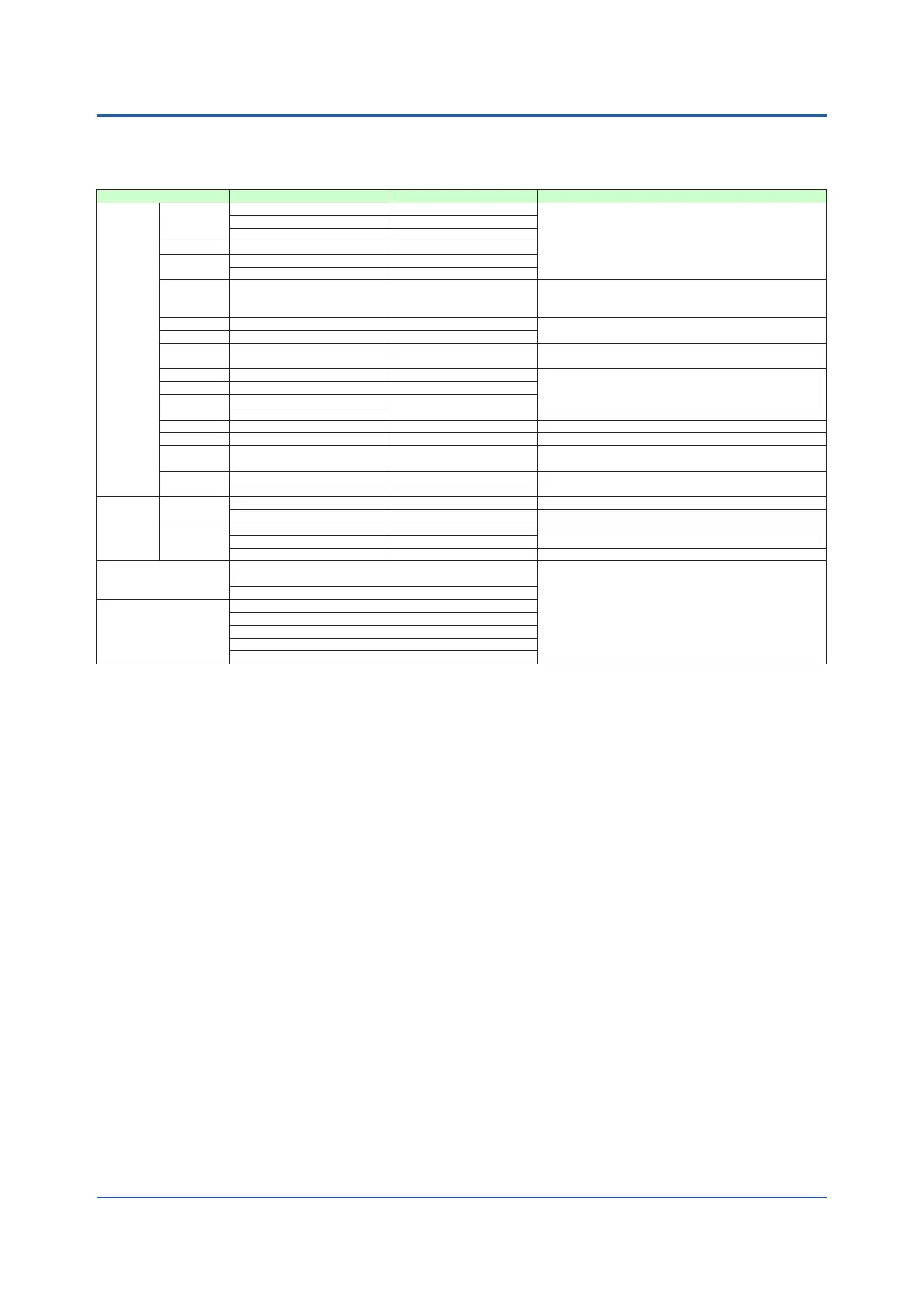
•Inputtype,instrumentrange,andmeasurementaccuracy:Seethetablebelow.
Input Type Instrument Range (°C) Instrument Range (°F) Accuracy
Thermo-
couple
K
-270.0 to 1370.0°C -450.0 to 2500.0°F
±0.1% of instrument range ±1 digit for 0°C or more
±0.2% of instrument range ±1 digit for less than 0°C
±2% of instrument range ±1 digit for less than -200.0°C
of thermocouple K
±1% of instrument range ±1 digit for less than -200.0°C
of thermocouple T
-270.0 to 1000.0°C -450.0 to 2300.0°F
-270.0 to 500.0°C -200.0 to 1000.0°F
J -200.0 to 1200.0°C -300.0 to 2300.0°F
T
-270.0 to 400.0°C -450.0 to 750.0°F
0.0 to 400.0°C -200.0 to 750.0°F
B 0.0 to 1800.0°C 32 to 3300°F
±0.15% of instrument range ±1 digit for 400°C or more
±5% of instrument range ±1 digit for less than
400°C
S 0.0 to 1700.0°C 32 to 3100°F
±0.15% of instrument range ±1 digit
R 0.0 to 1700.0°C 32 to 3100°F
N -200.0 to 1300.0°C -300.0 to 2400.0°F
±0.1% of instrument range ±1 digit
±0.25% of instrument range ±1 digit for less than 0°C
E -270.0 to 1000.0°C -450.0 to 1800.0°F
±0.1% of instrument range ±1 digit for 0°C or more
±0.2% of instrument range ±1 digit for less than 0°C
±1.5% of instrument range ±1 digit for less than -
200.0°C of thermocouple E.
L -200.0 to 900.0°C -300.0 to 1600.0°F
U
-200.0 to 400.0°C -300.0 to 750.0°F
0.0 to 400.0°C -200.0 to 1000.0°F
W 0.0 to 2300.0°C 32 to 4200°F ±0.2% of instrument range ±1 digit (Note 2)
Platinel 2 0.0 to 1390.0°C 32.0 to 2500.0°F ±0.1% of instrument range ±1 digit
PR20-40 0.0 to 1900.0°C 32 to 3400°F
±0.5% of instrument range ±1 digit for 800°C or more
Accuracy is not guaranteed for less than 800°C.
W97Re3-
W75Re25
0.0 to 2000.0°C 32 to 3600°F ±0.2% of instrument range ±1 digit
RTD
JPt100
-200.0 to 500.0°C -300.0 to 1000.0°F ±0.1% of instrument range ±1 digit (Note 1)
-150.00 to 150.00°C -200.0 to 300.0°F ±0.1% of instrument range ±1 digit
Pt100
-200.0 to 850.0°C -300.0 to 1560.0°F
±0.1% of instrument range ±1 digit (Note 1)
-200.0 to 500.0°C -300.0 to 1000.0°F
-150.00 to 150.00°C -200.0 to 300.0°F ±0.1% of instrument range ±1 digit
Standard signal
0.400 to 2.000 V
±0.1% of instrument range ±1 digit
1.000 to 5.000 V
4.00 to 20.00 mA
DC voltage/current
0.000 to 2.000 V
0.00 to 10.00 V
0.00 to 20.00 mA
-10.00 to 20.00 mV
0.0 to 100.0 mV
The accuracy is that in the standard operating conditions: 23±2°C, 55±10%RH, and power frequency at 50/60 Hz.
Note1:±0.3°C±1digitintherangebetween0and100°C,±0.5°C±1digitintherangebetween-100and200°C.
Note 2: W: W-5% Re/W-26% Re(Hoskins Mfg.Co.). ASTM E988
• Input sampling (control) period: 200 ms
• Burnout detection:
Functions at TC, RTD, and standard signal.
Upscale,downscale,andoffcanbespecied.
Forstandardsignal,burnoutisdeterminedtohave
occurred if it is 0.1 V or 0.4 mA or less.
•Inputbiascurrent:0.05µA(forTCorRTD)
•Measuredcurrent(RTD):About0.16mA
• Input resistance:
TCormVinput:1MΩormore
Vinput:About1MΩ
mAinput:About250Ω
•Allowablesignalsourceresistance:
TCormVinput:250Ωorless
Effectsofsignalsourceresistance:0.1µV/Ωorless
DCvoltageinput:2kΩorless
Effectsofsignalsourceresistance:About0.01%/100Ω
•Allowablewiringresistance:
RTDinput:Max.150Ω/wire(Theconductor
resistancebetweenthethreewiresshallbeequal.)
Wiringresistanceeffect:±0.1ºC/10Ω
•Allowableinputvoltage/current:
TC, mV, mA and RTD input: ±10 V DC
V input: ±20 V DC
mA input: ±40 mA
• Noise rejection ratio:
Normal mode: 40 dB or more (at 50/60 Hz)
Common mode: 120 dB or more (at 50/60 Hz)
For100-240VAC,thepowerfrequencycanbeset
manually.
Automaticdetectionisalsoavailable.
For24VAC/DC,thepowerfrequencycanbeset
manually.
• Reference junction compensation error:
±1.0ºC (15 to 35ºC)
±1.5ºC (-10 to 15ºC and 35 to 50ºC)
•Applicablestandards:JIS/IEC/DIN(ITS-90)forTC
and RTD
ContactInputSpecications
•Numberofinputs:SeethetableofModelandSufx
Codes.
• Input type: No-voltage contact input or transistor
contact input
• Input contact rating: 12 V DC, 10 mA or more
Use a contact with a minimum on-current of 1 mA or
less.
• ON/OFF detection:
No-voltage contact input:
Contactresistanceof1kΩorlessisdeterminedas
“ON”andcontactresistanceof50kΩormoreas
“OFF.”
Transistor contact input:
Input voltage of 2 V or less is determined as “ON”
andleakagecurrentmustnotexceed100µAwhen
“OFF.”
• Minimum status detection hold time: Control period
+50 ms
• Use: PTNO. switch, operation mode switch, and
event input

 Loading...


