12
All Rights Reserved. Copyright © 2010, Yokogawa Electric Corporation
GS 05P02D41-01EN Mar.14,2016-00
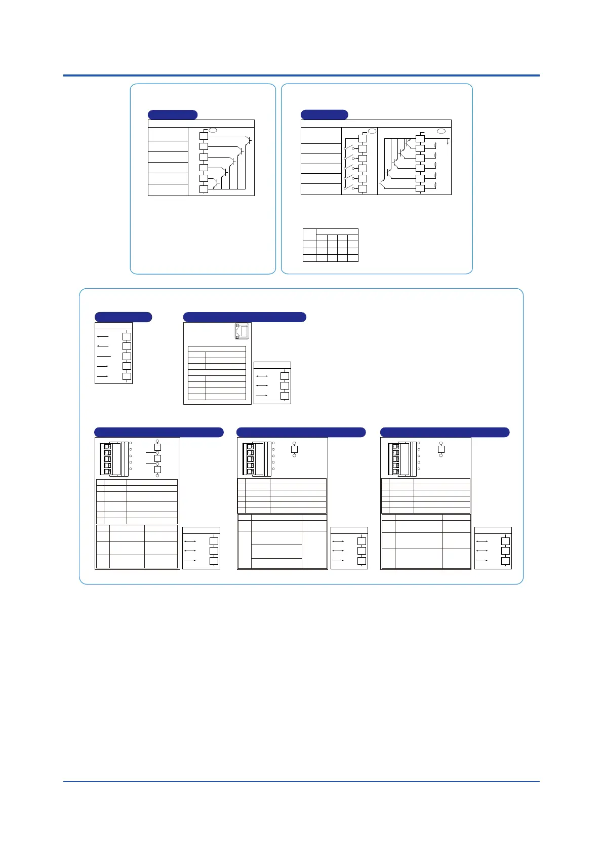
E1-Terminal Area
301-306
E4-Terminal Area
501-506
Program patterns can be selected according to
the combination of ON and OFF contact inputs.
Program pattern no.
1 2 3 4
DI41 ON OFF ON OFF
DI42 OFF ON ON OFF
DI43 OFF OFF OFF ON
(Suffix code: Type 2=1)
Contact input
External contact input
DI41
DI42
DI43
DI44
DI45
COM
Common
DI41
DI42
COM
+5V
+5V
No-voltage
contact
Transistor contact
Contact rating: 12 V DC, 10 mA or more
DI43
+5V
DI44
+5V
DI45
+5V
Factory default: No function
Factory default: No function
UP UP
501
502
503
504
505
506
501
502
503
504
505
506
Function can be assigned to the
terminals with no function.
DI
Bit-0 of
program pattern number
Bit-1 of
program pattern number
Bit-2 of
program pattern number
(Suffix code: Type 2=1)
Contact output
External contact output
DO12
DO11
DO13
DO14
DO15
COM
Common
UP
301
302
303
304
305
306
DO
Transistor contact rating: 24 V DC, 50 mA
Function can be assigned to the
terminals with no function.
Time event-3 output
Time event-4 output
Alarm-2
Alarm-1
Time event-2 output
(Suffix code: Type 3=2)
Ethernet communication (with gateway function)
10BASE-T/100BASE-TX
RJ45 connector
Color
Lit
Unlit
Amber
100M bps
10M bps
Green
Linked
Active
Link failure
Color
Lit
Blink
Unlit
Upper side LED (baud rate)
Lower side LED (link activity)
RS-485
RSB(+)
RSA(-)
SG
407
408
409
ETHR
RS-485
SDB(+)
SDA(-)
RDB(+)
RDA(-)
SG
RS
-
485 communication
(Suffix code:
Type 3=1)
407
408
409
410
411
RS485
(Suffix code: Type 3=4)
PROFIBUS-DP communication (with Modbus master)
Pin
1
2
Signal name Description
VP
RxD/TxD-P
3 RxD/TxD-N
4 DGND
5 SHIELD
+5V bus power
Data signal
(positive data receive/transmit)
Data signal
(negative data recive/transmit)
Signal ground
Shield ground
RS-485
RSB(+)
RSA(-)
SG
407
408
409
PROF
If the UT is located at the end
of a segment for the
PROFIBUS
communication wiring,
terminating resistors are
separately needed.
These are to be prepared by
users. (390 Ω: 2 pcs. 220 Ω:
1 pc., or an active
terminator.)
VP
RxD/TxD-P
Data
line
Data
line
390Ω
220Ω
390Ω
RxD/TxD-N
DGND
CHK
RDY
ERR
1
2
3
4
5
LED
CHK
(red)
RDY
(green)
Lit
Unlit
ERR
(red)
User profile error Normal
Normal
Not connected, or
communication
failure (flashing)
Normal
Communicating
successfully
No electricity, or
Communication
failure
E3-Terminal Area
401-412
(Suffix code: Type 3=5)
DeviceNet communication (with Modbus master)
RS-485
RSB(+)
RSA(-)
SG
407
408
409
DNET
If the UT is located at
the end of a segment
for the DeviceNet
communication wiring,
terminating resistors
are separately needed.
These are to be
prepared by users.
(121 Ω: 1 pc.)
CAN_H
CAN_L
121Ω
LED
CHK
(red)
MNS
(green
/red)
Lit/flashing
Unlit
User profile error
Normal
Pin
1
2
Signal name Description
CAN_H
CAN_L
3
V+
4
V-
5
DRAIN
RX/TX + signal
RX/TX - signal
Shield/Drain wire
DeviceNet power supply 24V
DeviceNet power supply common
Normal, communicating
successfully (green, lit).
Not connected (green, flashing).
Critical link failure (red, lit).
Connection timeout (red, flashing)
At power-on/Communication
faulted (green/red, flashing)
No electricity
CHK
MNS
1
2
3
4
5
(Suffix code: Type 3=3)
CC-Link communication (with Modbus master)
RS-485
RSB(+)
RSA(-)
SG
407
408
409
CC-L
If the UT is located at
the end of a segment
for the CC-Link
communication wiring,
terminating resistors
are separately needed.
These are to be
prepared by users.
(110 Ω: 1 pc.)
DA
DB
110Ω
LED
CHK
(red)
L ERR
(red)
L RUN
(green)
Lit
Unlit
User profile error/
Address error
Normal
Normal
Pin
1
2
Signal name Description
DA
DB
3 DG
4
SLD
5
FG
TX signal
RX signal
Flame ground
TX/RX signal ground
Shield
Normal
Communicating successfully
Communication failure
(CRC error)
No carrier
detected/
Communication
timeout
CHK
L RUN
L ERR
1
2
3
4
5

 Loading...


