2 - 54 MP7000 Scanner Scale Integrator Guide
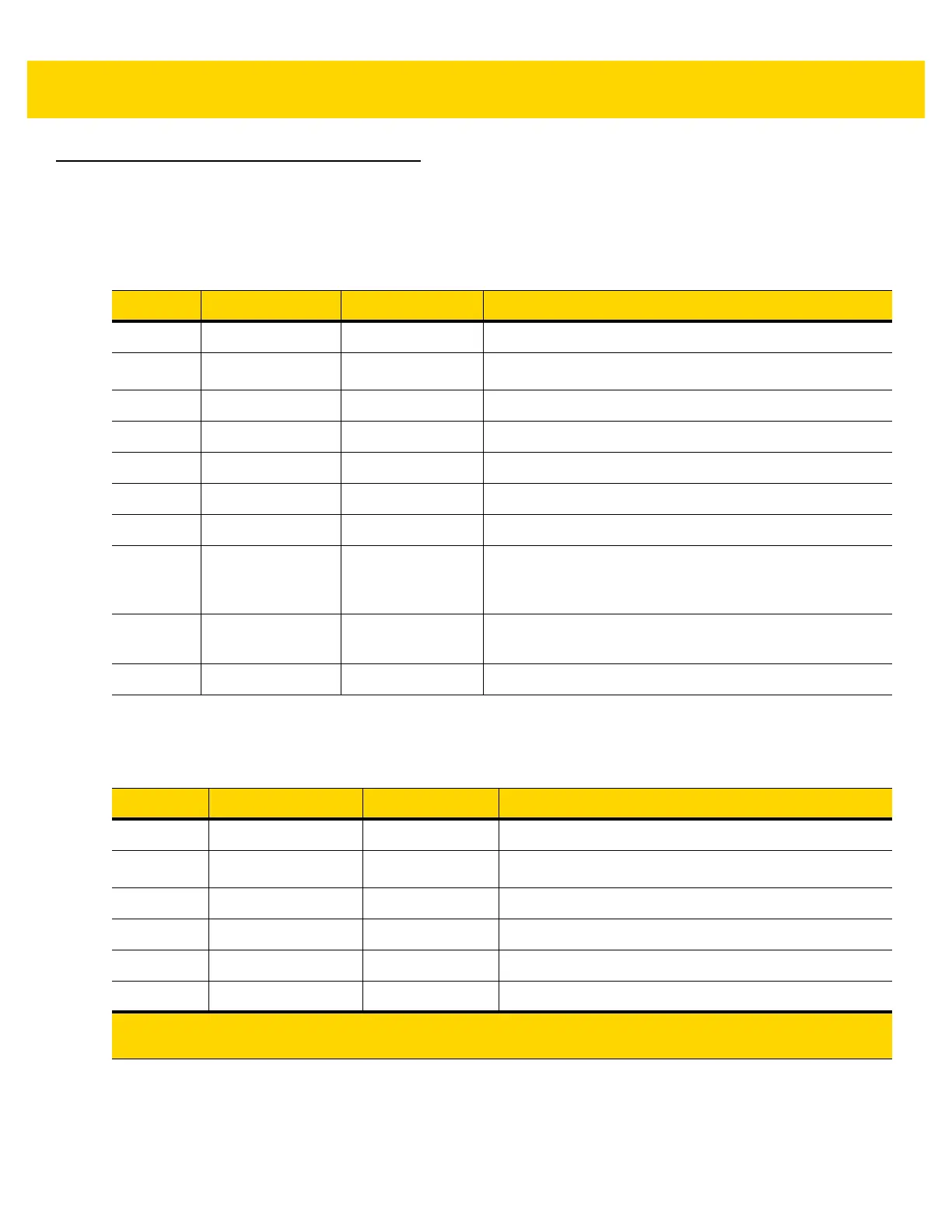
Connector Pins
RS-232 AUX 1
Scale Display Port
Table 2-10 RJ-45
Pin # Signal/Name Direction Description
1 N/C N/A No Connection
25V Out
RS-232 scanner 5VDC Supply*
3 GND N/A Signal Ground
4 TXD Out Serial TXD (±5.4V)
5 RXD In Serial RXD (±5.4V)
6 RTS Out Serial RTS (±5.4V)
7 CTS In Serial CTS (±5.4V)
8 Scale LED In Indicates price computational scale has returned to zero -
reflected in UI Scale Status LED (if enabled). I/O signals
are 5V TTL.
9 Scale Zero Out Zeros price computational scale when the Zero UI button
is pressed (if enabled). I/O signals are 5V TTL.
10 12V/150mA Out Power output for price computational scale.
Table 2-11 RJ-11, Scale Display
Pin # Signal/Name Direction Description
1 DEBUG_TXD Out Debug serial TX
25V Out
Auxiliary 5V output *
3 TXD Out Scale Display serial TX (3.3V TTL)
4 RXD In Scale Display serial RX (3.3V TTL)
5 GND N/A Signal ground
6 DEBUG_RXD In Debug serial RX
* The total combined current for the USB and RS-232 peripheral ports should be less than 750mA total auxiliary
current. Each individual port should not exceed 500mA.