Host Interfaces and Cable Pinouts 2 - 55
RS-232 AUX 2
Checkpoint Interlock
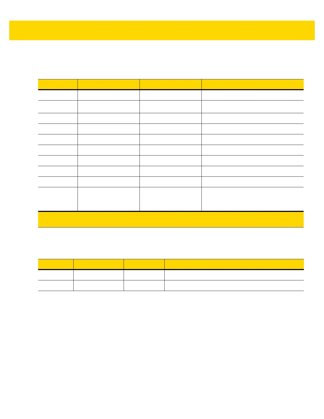
Table 2-12 RJ-45
Pin # Signal/Name Direction Description
1 N/C N/A No connection
25V Out
RS-232 scanner 5V supply *
3 GND N/A Signal ground
4 TXD Out Serial TXD (±5.4V)
5 RXD In Serial RXD (±5.4V)
6 RTS Out Serial RTS (±5.4V)
7 CTS In Serial CTS (±5.4V)
8 N/C N/A No connection
9 N/C N/A No connection
10 12V/150mA Out Output for auxiliary device.
NOTE 150mA maximum available between
both AUX 1 and AUX 2.
*The total combined current for the USB and RS-232 peripheral ports should be less than 750mA total auxiliary
current. Each individual port should not exceed 500mA.
Table 2-13 EAS Interlock Connector
Pin # Signal/Name Direction Description
1 Interlock Out Checkpoint EAS Interlock (5V 4mA PNP collector out)
2 GND N/A Signal ground