Z8 Microcontrollers
ZiLOG Instruction Set
UM001601-0803 12-7
Additional symbols used are:
Assignment of a value is indicated by the symbol “¨”. For exam-
ple,
dst ¨ dst + src
indicates the source data is added to the destination data and the
result is stored in the destination location.
The notation 'addr(n)' is used to refer to bit'n' of a given location.
For example,
dst (7)
refers to bit 7 of the destination operand.
12.4.1 Assembly Language Syntax
For proper instruction execution, Z8 assembly language syntax
requires ‘dst, src’ be specified, in that order. The following in
-
struction descriptions show the format of the object code pro-
duced by the assembler. This binary format should be followed
by users who prefer manual program coding or who intend to im
-
plement their own assembler.
Example: If the contents of registers 43H and 08H are added and
the result is stored in 43H, the assembly syntax and resulting ob
-
ject code is:
In general, whenever an instruction format requires an 8-bit reg-
ister address, that address can specify any register location in the
range 0 - 255 or a Working Register R0 - R15. If, in the above
example, register 08H is a Working Register, the assembly syn
-
tax and resulting object code would be:
Note: See the device product specification to determine the
exact register file range available. The register file size varies by
device type
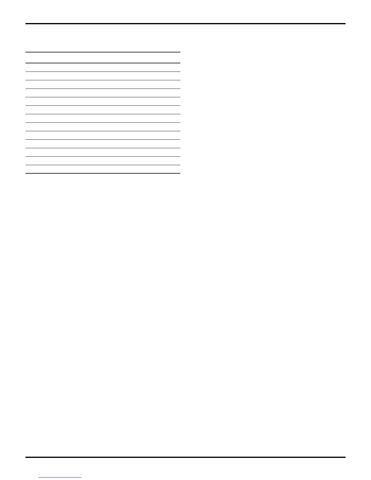
Tab le 12-13. Additional Symbols
Symbol Definition
dst Destination Operand
src Source Operand
@ Indirect Address Prefix
SP Stack Pointer
PC Program Counter
FLAGS Flag Register (FCH)
RP Register Pointer (FDH)
IMR Interrupt Mask Register (FBH)
# Immediate Operand Prefix
% Hexadecimal Number Prefix
H Hexadecimal Number Suffix
B Binary Number Suffix
OPC Opcode
ASM: ADD 43H, 08H (ADD dst, src)
OBJ: 04 08 43 (OPC src, dst)
ASM: ADD 43H, 08H (ADD dst, src)
OBJ: 04 08 43 (OPC src, dst)