Z8 Microcontrollers
Reset—Watch-Dog Timer ZiLOG
4-2 UM001601-0803
4.2 RESET PIN, INTERNAL POR OPERATION (Continued)
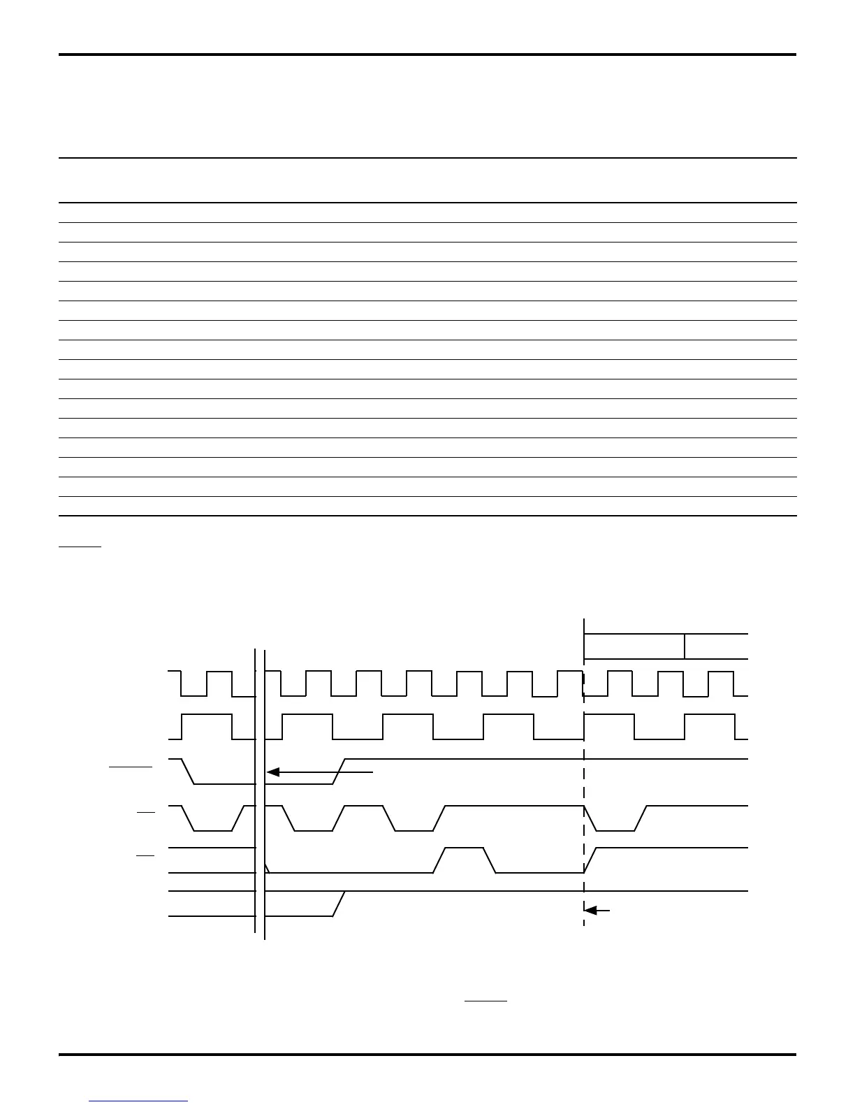
Program execution starts 5 to 10 clock cycles after internal
RESET has returned High. The initial instruction fetch is from
location 000CH. Figure 4-1 shows reset timing.
After a reset, the first routine executed should be one that initial-
izes the control registers to the required system configuration.
The RESET pin is the input of a Schmitt-triggered circuit. Reset-
ting the Z8 will initialize port and control registers to their de-
Table 4-1. Sample Control and Peripheral Register Reset Values (ERF Bank 0)
Register Register Bits
(HEX) Name 7 6 5 4 3 2 1 0 Comments
F0 Serial I/O U U U U U U U U
F1 Timer Mode 0 0 0 0 0 0 0 0 Counter/Timers Stopped
F2 Counter/Timer1 U U U U U U U U
F3 T1 Prescaler U U U U U U 0 0 Single-Pass Count Mode, External Clock Source
F4 Counter/Timer0 U U U U U U U U
F5 T0 Prescaler U U U U U U U 0 Single-Pass Count Mode
F6 Port 2 Mode 1 1 1 1 1 1 1 1 All Inputs
F7 Port 3 Mode 0 0 0 0 0 0 0 0 Port 2 Open-Drain, P33–P30 Input, P37–P34 Output
F8 Port 0–1 Mode 0 1 0 0 1 1 0 1 Internal Stack, Normal Memory Timing
F9 Interrupt Priority U U U U U U U U
FA Interrupt Request 0 0 0 0 0 0 0 0 All Interrupts Cleared
FB Interrupt Mask 0 U U U U U U U Interrupts Disabled
FC Flags U U U U U U U U
FD Register Pointer 0 0 0 0 0 0 0 0
FE Stack Pointer (High) U U U U U U U U
FF Stack Pointer (Low) U U U U U U U U
Figure 4-1. Reset Timing
First Machine Cycle
T1
Clock
RESET
AS
DS
R/W
First Instruction Fetch
Hold Low For 4 SCLK
Periods (Minimum)
SCLK

 Loading...
