Z8 Microcontrollers
ZiLOG Reset—Watch-Dog Timer
UM001601-0803 4-3
fault states. To form the internal reset line, the output of the trig-
ger is synchronized with the internal clock. The clock must
therefore be running for
RESET to function. It requires 4 internal
system clocks after reset is detected for the Z8 to reset the inter
-
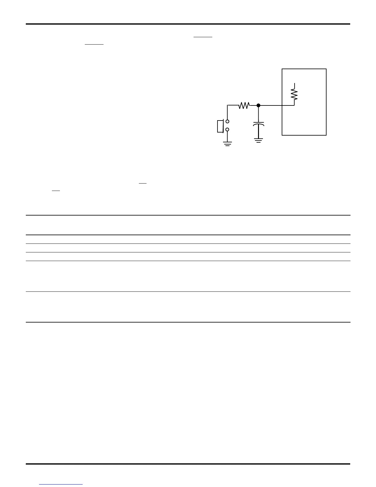
nal circuitry. An internal pull-up, combined with an external ca-
pacitor of 1 uf, provides enough time to properly reset the Z8
(Figure 4-2). In some cases, the Z8 has an internal POR timer
circuit that holds the Z8 in reset mode for a duration (T
POR
) be-
fore releasing the device out of reset. On these Z8 devices, the
internally generated reset drives the reset pin low for the POR
time. Any devices driving the reset line must be open-drained in
order to avoid damage from possible conflict during reset condi
-
tions. This reset time allows the on-board clock oscillator to sta-
bilize.
To avoid asynchronous and noisy reset problems, the Z8 is
equipped with a reset filter of four external clocks (4TpC). If the
external reset signal is less than 4TpC in duration, no reset oc
-
curs. On the fifth clock after the reset is detected, an internal
RST signal is latched and held for an internal register count of
18 external clocks, or for the duration of the external reset,
whichever is longer. During the reset cycle,
DS is held active
low while
AS cycles at a rate of the internal system clock. Pro-
gram execution begins at location 000CH, 5-10 TpC cycles after
RESET is released. For the internal Power-On Reset, the reset
output time is specified as T
POR
. Please refer to specific product
specifications for actual values.
Figure 4-2. Example of External Power-On Reset Circuit
1 µF
+5V
100 KΩ
/RESET
1K
to
200 KΩ
10 V
Table 4-2. Expanded Register File Bank 0 Reset Values at RESET
Register Register Bits
(HEX) Name 7 6 5 4 3 2 1 0 Comments
00 Port 0 U U U U U U U U Input mode, output set to push-pull
01 Port 1 U U U U U U U U Input mode, output set to push-pull
02 Port 2 U U U U U U U U Input mode, output set to open drain
03 Port 3 1 1 1 1 U U U U Standard Digital input and output
Z86L7X Family Device Port P34-P37 = 0
(Except Z86L70/71/75)
All other Z8 = 1
04–EF General-
Purpose
Registers
04-EF
U U U U U U U U Undefined

 Loading...
