GDP-32
II
INSTRUCTION MANUAL
May 2002 Section 17, Page 4
THE DIAGNOSTICS PROGRAM
Running Diagnostics:
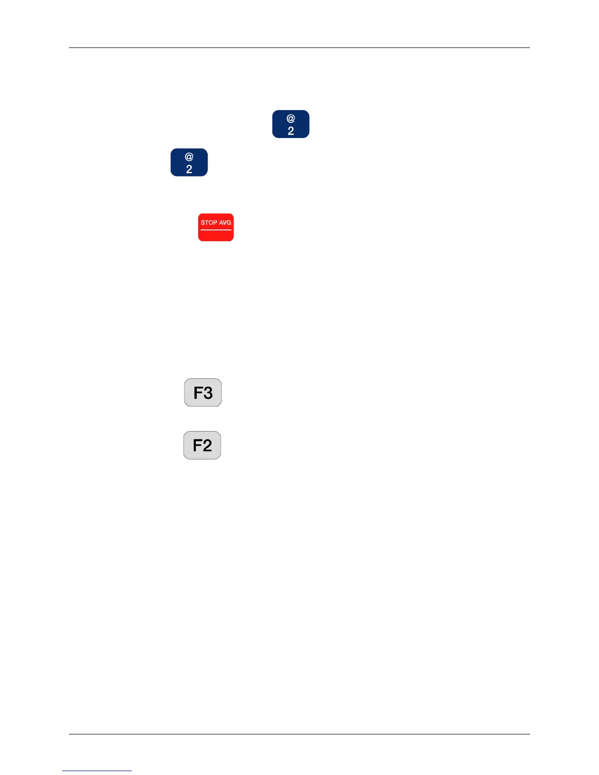
1. From the Main Menu press , Utilities.
2. Press , Diagnostics. If the receiver has just been turned on and no
Survey Programs have been started, the screen appears as shown above in Figure
17.2 (a).
NOTE: Press
Escape
to leave diagnostic mode and return to the Main Program
Menu.
There are three areas of the Diagnostic Screen:
a) Timing (top left)
b) Calibrate (bottom left)
c) Analog Boards (right)
3. To move between screen menu sections use the two activated Special Function
Keys:
a) The , NEXT key circulates in a counter-clockwise motion from
Timing to Calibrate to Analog Board menu sections of the screen.
b) The , PREV key rotates between the three menu sections in the
opposite direction (Analog to Calibrate to Timing).
4. Use the Cursor Control keys to move through the screen sections and change
parameters.
Timing Diagnostic Fields
Frequency (Freq)
The frequency (period) is changed in binary steps from 0.00097656 Hz (.001 Hz on
the display) to 8192 Hz.
External Monitoring - The period waveform (shown schematically in Figure 17.1)
corresponding to the selected frequency can be observed by monitoring connector J3
pin 6 (PERIOD on the timing card). Connector J3 connects the calibrate and timing
card to the TRANSMITTER I/O connector located on the left hand side of the GDP-
32
II
case, and this signal can be observed on pin D. The signal is also available on the
64-pin DIN bus connector J1 pin A7.
Sample Rate (SR)
The ADC sample rate can be set to a selected value from 1 Hz to 32,768 Hz.