EKI-7710 Series User Manual 25
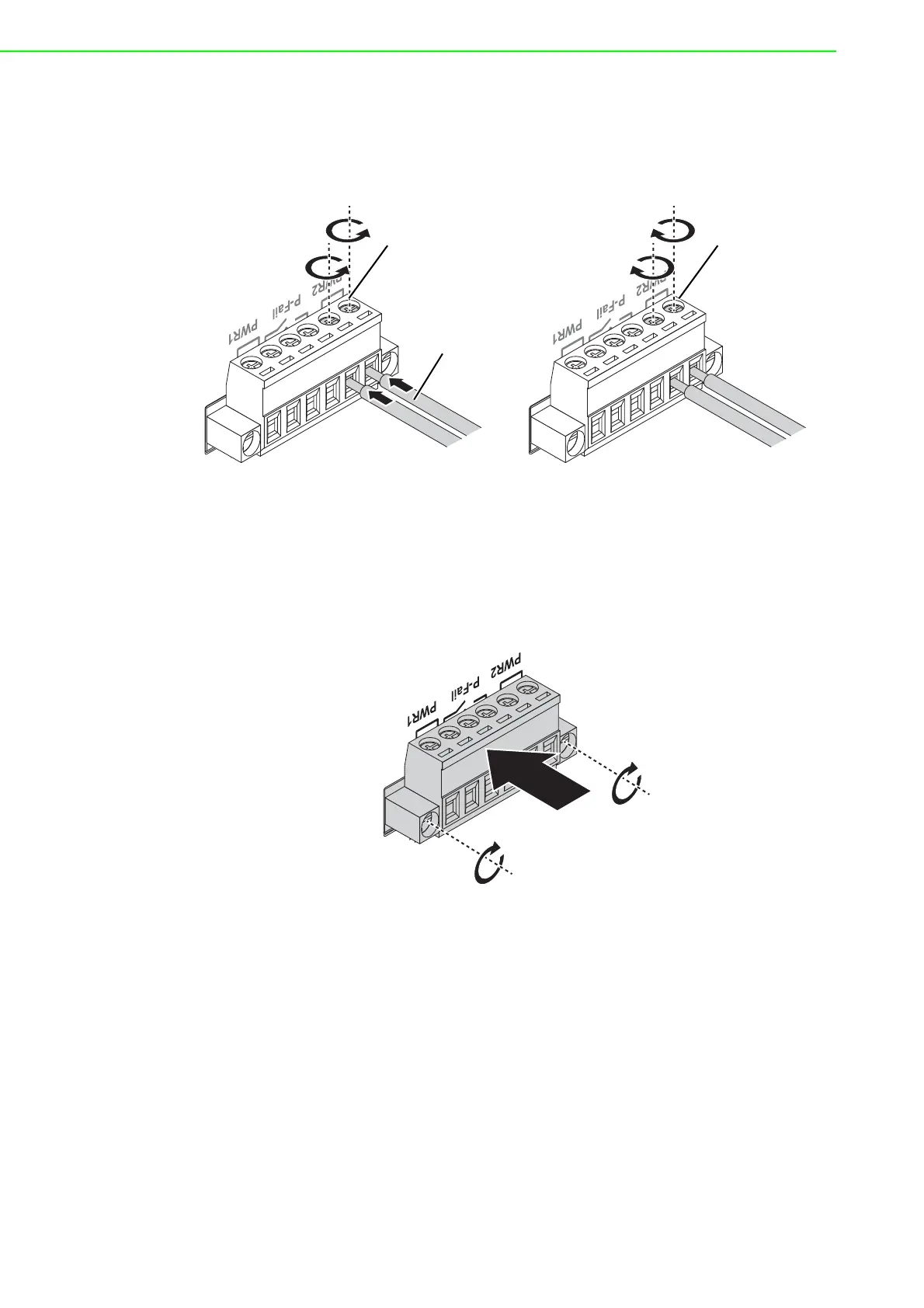
3. Insert a small flat-bladed screwdriver in the V1+/V1- wire-clamp screws, and
loosen the screws.
4. Insert the negative/positive DC wires into the V+/V- terminals of PW1. If setting
up power redundancy, connect PW2 in the same manner.
5. Tighten the wire-clamp screws to secure the DC wires in place.
Figure 2.22 Installing DC Wires in a Terminal Block
6. Align the terminal block over the terminal block receptor on the switch.
7. Insert the terminal block and press it in until it is flush with the terminal block
receptor.
8. Tighten the screws on the terminal block to secure it to the terminal block recep-
tor.
If there is no gap between the terminal block and the terminal receptor, the ter-
minal block is seated correctly.
Figure 2.23 Securing a Terminal Block to a Receptor
1A@24V
Loosening
Wire-clamp
Screws
Installing DC
Wires
Securing Wire-
clamp Screws