55
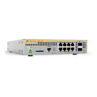
Figure 1: GS980MX/10HSm Front Panel .............................................................................................................................18
Figure 2: GS980MX/18HSm Front Panel .............................................................................................................................18
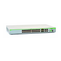
Figure 3: GS980MX/28 Front Panel .....................................................................................................................................18
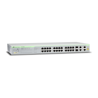
Figure 4: GS980MX/28PSm Front Panel..............................................................................................................................19
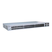
Figure 5: GS980MX/52 Front Panel .....................................................................................................................................19
Figure 6: GS980MX/52PSm Front Panel..............................................................................................................................19
Figure 7: GS980MX/10HSm Back Panel .............................................................................................................................20
Figure 8: GS980MX/18HSm and GS980MX/52 Back Panel ................................................................................................20
Figure 9: GS980MX/28 and GS980MX/52 Back Panel ........................................................................................................20
Figure 10: GS980MX/28PSm and GS980MX/52PSm Back Panel.......................................................................................20
Figure 11: Management Panel .............................................................................................................................................21
Figure 12: GS980MX/10HSm Twisted Pair Ports.................................................................................................................35
Figure 13: GS980MX/18HSm Twisted Pair Ports.................................................................................................................36
Figure 14: GS980MX/28 Twisted Pair Ports 1-24 LEDs.......................................................................................................38
Figure 15: GS980MX/28PSm Twisted Pair Ports 1-24 LEDs ...............................................................................................39
Figure 16: GS980MX/52 Twisted Pair Ports 1-48 LEDs.......................................................................................................40
Figure 17: GS980MX/52PSm Twisted Pair Ports 1-48 LEDs ...............................................................................................41
Figure 18: Link and Activity LEDs for the 1Gbps SFP/10Gbps SFP+ Ports.........................................................................48
Figure 19: Switch ID LED .....................................................................................................................................................52
Figure 20: Switch ID LED Description ..................................................................................................................................53
Figure 21: Valid Stack Trunk Using Default Stacking Ports 9 to 10 on 10-Port Switches ....................................................65
Figure 22: Valid Stack Trunk Using Default Stacking Ports 17 to 18 on 18-Port Switches ..................................................66
Figure 23: Valid Stack Trunk Using Default Stacking Ports 27 to 28 on 28-Port Switches ..................................................67
Figure 24: Valid Stack Trunk Using Default Stacking Ports 51 to 52 on 52-Port Switches ..................................................68
Figure 25: Stack Trunks of Ports 25 to 28 ............................................................................................................................70
Figure 26: Valid Stack Trunk Using a Combination of Ports 25 to 28 and Ports 49 to 52 ....................................................71
Figure 27: Valid 10Gbps Stack Trunk with Both Fiber Optic and SP10TW Direct Connect Cables.....................................72
Figure 28: Trunks of 5Gbps Ports for Stacks of Two GS980MX/28PSm Switches ..............................................................74
Figure 29: Trunks of 5Gbps Ports for Stacks of Three GS980MX/28PSm Switches ...........................................................75
Figure 30: Trunks of 5Gbps Ports for Stacks of Four GS980MX/28PSmSwitches ..............................................................76
Figure 31: Invalid Stack Trunk with an Intermediary Networking Device..............................................................................77
Figure 32: Invalid Stack Trunk with One Port Used Per Switch............................................................................................77
Figure 33: Invalid Stack Trunk with Different Numbers of Links ...........................................................................................78
Figure 34: Invalid Stack Trunk with Different Port Types......................................................................................................78
Figure 35: GS980MX/10HSm Switch Shipping Box .............................................................................................................94
Figure 36: GS980MX/10HSm Accessory Kit ........................................................................................................................95
Figure 37: GS980MX/10HSm Accessory Kit (Continued) ....................................................................................................96
Figure 38: GS980MX/18HSm Switch Shipping Box .............................................................................................................97
Figure 39: GS980MX/18HSm Switch Accessory Kit.............................................................................................................98
Figure 40: 24- and 48-Port Switch Shipping Box..................................................................................................................99
Figure 41: Accessory Kit Items...........................................................................................................................................100
Figure 42: Parts of the Bumper Feet ..................................................................................................................................102
Figure 43: Holes for Bumper Feet ......................................................................................................................................102
Figure 44: Inserting the Rivet Housing into the Bumper Foot............................................................................................. 103
Figure 45: Placing the Bumper Foot on a Base Corner Hole .............................................................................................103
Figure 46: Inserting the Rivet into the Bumper Foot ...........................................................................................................104
Figure 47: RKMT-J14 Brackets and Switch........................................................................................................................106
Figure 48: RKMT-J15 Bracket ............................................................................................................................................106
Figure 49: RKMT-J15 Bracket with Switches .....................................................................................................................107
Figures
 Loading...

