A20 User Manual (Revision 1.2) Copyright © 2013 Allwinner Technology Co., Ltd. All Rights Reserved. Page 115 / 812
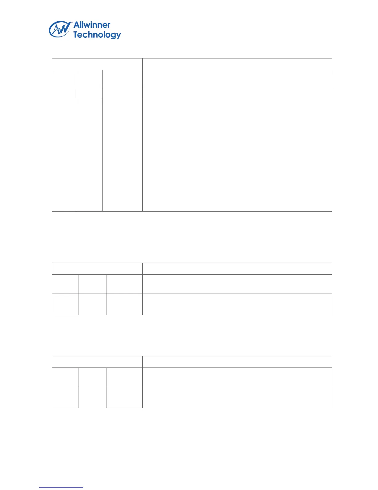
Register Name: TMR1_CTRL_REG
0: No effect, 1: Reload timer 1 Interval value.
TMR1_EN.
Timer 1 Enable.
0: Stop/Pause, 1: Start.
If the timer is started, it will reload the interval value to internal
register, and the current counter will count from interval value to
0.
If the current counter does not reach the zero, the timer enable
bit is set to “0”, the current value counter will pause. At least wait
for 2 Tcylces, the start bit can be set to 1.
In timer pause state, the interval value register can be modified.
If the timer is started again, and the Software hope the current
value register to down-count from the new interval value, the
reload bit and the enable bit should be set to 1 at the same time.
Note: the time between the timer disabled and enabled should be larger than 2*Tcycles(Tcycles=
Timer clock source/pre-scale).
1.9.3.7. TIMER 1 INTERVAL VALUE REGISTER
Register Name: TMR1_INTV_VALUE_REG
TMR1_INTV_VALUE.
Timer 1 Interval Value.
Note: the value setting should take into consideration the system clock and the timer clock source.
1.9.3.8. TIMER 1 CURRENT VALUE REGISTER
Register Name: TMR1_CUR_VALUE_REG
TMR1_CUR_VALUE.
Timer 1 Current Value.
Note: Timer 1 current value is a 32-bit down-counter(from interval value to 0). This register can be
read correctly if the PCLK is faster than 2*TimerFreq(TimerFreq = TimerClkSource/pre-scale).