A20 User Manual (Revision 1.2) Copyright © 2013 Allwinner Technology Co., Ltd. All Rights Reserved. Page 181 / 812
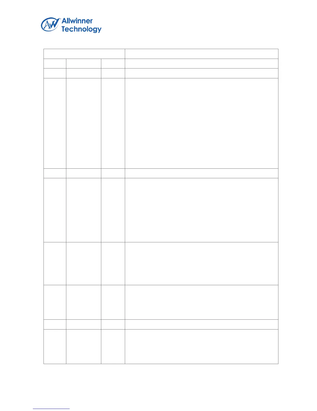
Register Name: AC_ADC_FIFOC
RX_FIFO_MODE.
RX FIFO Output Mode (Mode 0, 1)
0: Expanding ‘0’ at LSB of TX FIFO register
1: Expanding received sample sign bit at MSB of TX FIFO
register
For 24-bits received audio sample:
Mode 0: RXDATA[31:0] = {FIFO_O[23:0], 8’h0}
Mode 1: Reserved
For 16-bits received audio sample:
Mode 0: RXDATA[31:0] = {FIFO_O[23:8], 16’h0}
Mode 1: RXDATA[31:0] = {16{FIFO_O[23]}, FIFO_O[23:8]}
RX_FIFO_TRG_LEVEL.
RX FIFO Trigger Level (RXTL[4:0])
Interrupt and DMA request trigger level for TX FIFO normal
condition
IRQ/DRQ Generated when WLEVEL
」セ
RXTL[4:0]
Notes:
WLEVEL represents the number of valid samples in the RX
FIFO
ADC_MONO_EN.
ADC Mono Enable.
0: Stereo, 16 levels FIFO
1: mono, 32 levels FIFO
When set to ‘1’, Only left channel samples are recorded
RX_SAMPLE_BITS.
Receiving Audio Sample Resolution
0: 16 bits
1: 24 bits
ADC_DRQ_EN.
ADC FIFO Data Available DRQ Enable.
0: Disable
1: Enable