A20 User Manual (Revision 1.2) Copyright © 2013 Allwinner Technology Co., Ltd. All Rights Reserved. Page 29 / 812
1.4.3.10. IDLE COUNTER 0 LOW REGISTER (DEFAULT: 0X00000000)
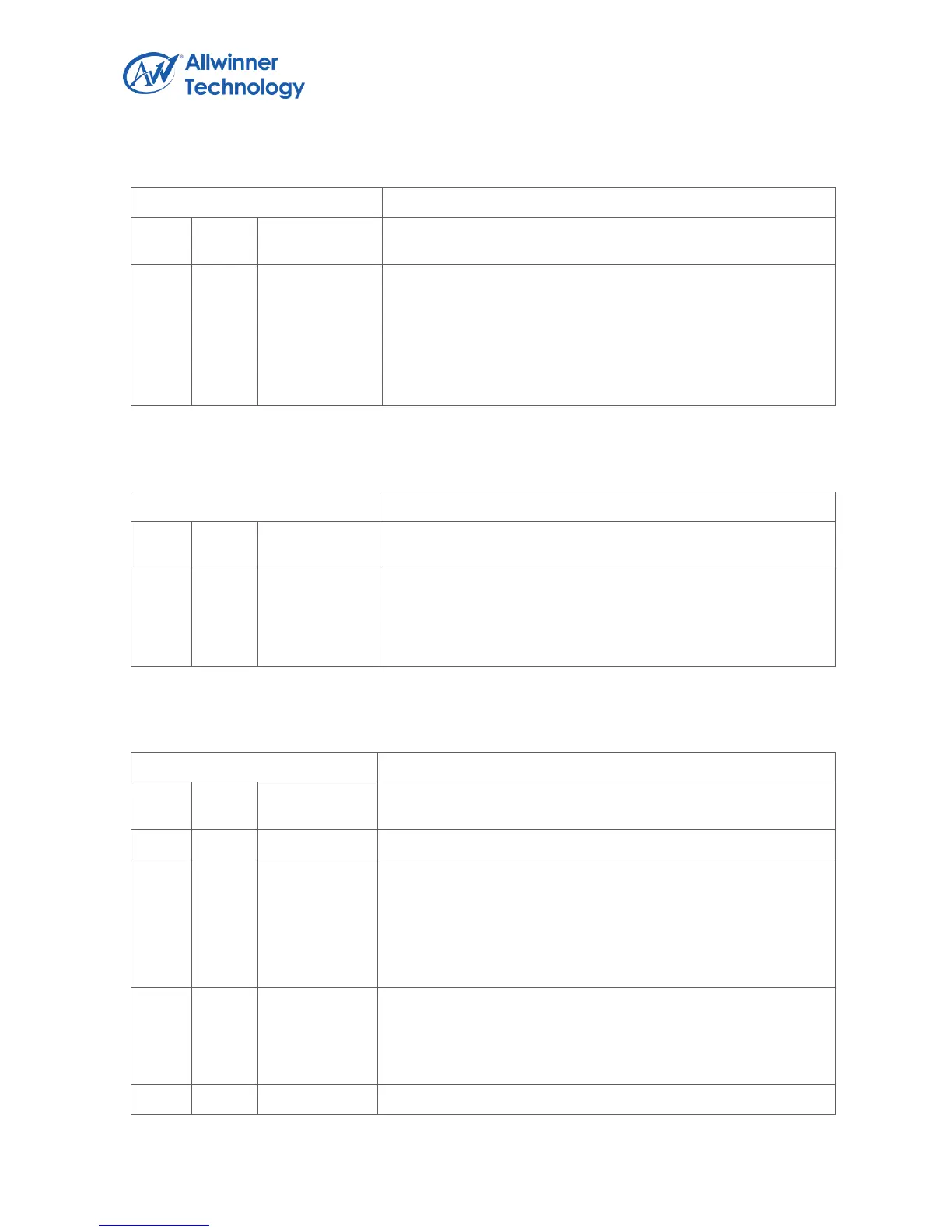
Register Name: IDLE_CNT0_LOW_REG.
IDLE_CNT0_LO.
Idle Counter 0 [31:0].
This counter clock source is 24MHz. If the CPU is in idle
state, the counter will count up in the clock of 24MHz.
Any write to this register will clear this register and the idle
counter 0 high register.
1.4.3.11. IDLE COUNTER 0 HIGH REGISTER (DEFAULT: 0X00000000)
Register Name: IDLE_CNT0_HIGH_REG
IDLE_CNT0_HI.
Idle Counter 0 [63:32].
Any write to this register will clear this register and the idle
counter 0 low register.
1.4.3.12. IDLE COUNTER 0 CONTROL REGISTER (DEFAULT: 0X00000000)
Register Name: IDLE_CNT0_CTRL_REG
IDLE_CNT_EN.
Idle counter enable.
0: disable
1: enable.
Note: Idle Counter 0 is used for CPU0
IDLE_RL_EN.
Idle Counter Read Latch Enable.
0: no effect, 1: to latch the idle Counter to the Low/Hi registers
and it will change to zero after the registers are latched.