A20 User Manual (Revision 1.2) Copyright © 2013 Allwinner Technology Co., Ltd. All Rights Reserved. Page 31 / 812
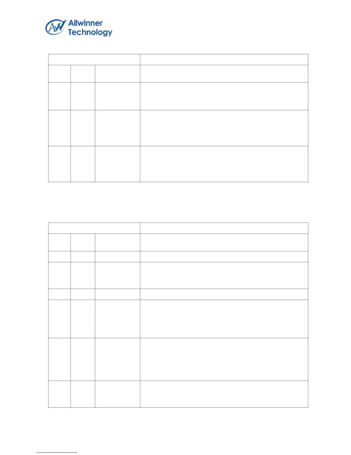
Register Name: IDLE_CNT1_CTRL_REG
0: disable
1: enable.
Note: Idle Counter 1 is used for CPU1
IDLE_RL_EN.
Idle Counter Read Latch Enable.
0: no effect, 1: to latch the idle Counter to the Low/Hi registers
and it will change to zero after the registers are latched.
IDLE_CNT_CLR_EN.
Idle Counter Clear Enable.
0: no effect, 1: to clear the idle Counter Low/Hi registers and it
will change to zero after the registers are cleared.
1.4.3.16. OSC24M 64-BIT COUNTER CONTROL REGISTER (DEFAULT: 0X00000000)
Register Name: OSC24M_CNT64_CTRL_REG
CNT64_SYNCH
Wite 1 then write 0 (a high pulse) to force the 64-bit system
counter synchronize the OSC24M 64-bit counter.
CNT64_CLK_SRC_SEL.
64-bit Counter Clock Source Select.
0: OSC24M
1: /
CNT64_RL_EN.
64-bit Counter Read Latch Enable.
0: no effect, 1: to latch the 64-bit Counter to the Low/Hi
registers and it will change to zero after the registers are
latched.
CNT64_CLR_EN.
64-bit Counter Clear Enable.
0: no effect, 1: to clear the 64-bit Counter Low/Hi registers and