EasyManua.ls Logo

Allwinner A20 - Page 336

Allwinner A20
812 pages
Print Icon
To Next Page IconTo Next Page
To Previous Page IconTo Previous Page
Loading...
A20 User Manual (Revision 1.2) Copyright © 2013 Allwinner Technology Co., Ltd. All Rights Reserved. Page 336 / 812
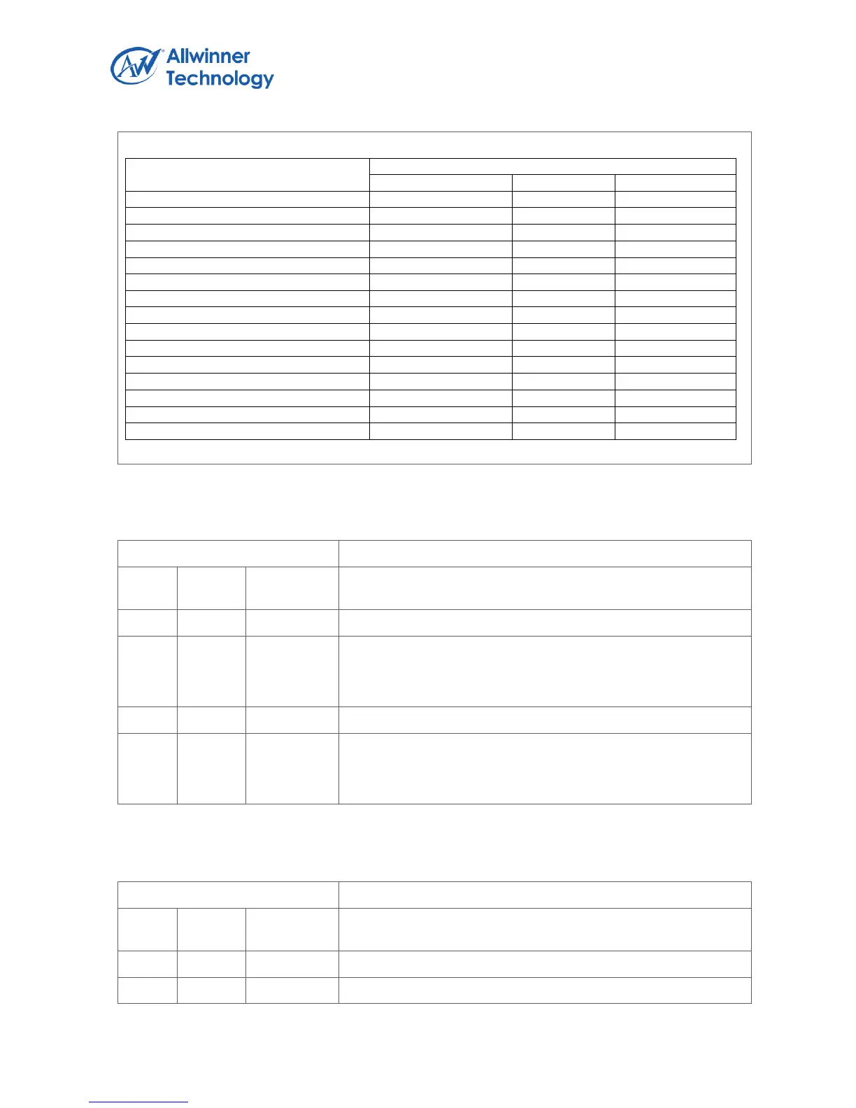
Output data mode and output data ports mapping:
Output data mode
Output data channel selection
Channel 0
Channel 1
Channel 2
A8R8G8B8 or interleaved AYUV8888
ARGB or AYUV
Ignore
Ignore
A4R4G4B4
ARGB
Ignore
Ignore
A1R5G5B5
ARGB
Ignore
Ignore
R5G6B5
RGB
Ignore
Ignore
interleaved YUV422
YUV
Ignore
Ignore
planar YUV422 (UV combined)
Y
UV
Ignore
planar YUV422
Y
U
V
8bpp MONO
MONO
Ignore
Ignore
4bpp MONO
MONO
Ignore
Ignore
2bpp MONO
MONO
Ignore
Ignore
1bpp MONO
MONO
Ignore
Ignore
planar YUV420 (UV combined)
Y
UV
Ignore
planar YUV420
Y
U
V
planar YUV411 (UV combined)
Y
UV
Ignore
planar YUV411
Y
U
V
3.1.4.28. OUTPUT SIZE REGISTER
Offset: 0xE8
Register Name: MP_OUTSIZE_REG
Bit
Read/W
rite
Default/He
x
Description
31:29
/
/
/
28:16
R/W
0
OUT_HEIGHT
Height
The value add 1 equal the actual output image height
15:11
/
/
/
12:0
R/W
0
OUT_WIDTH
Width
The value add 1 equal the actual output image width
3.1.4.29. OUTPUT ADDRESS HIGH 4BITS REGISTER
Offset: 0xEC
Register Name: MP_OUTH4ADD_REG
Bit
Read/W
rite
Default/He
x
Description
31:20
/
/
/
19:16
R/W
0
OUTCH2_H4ADD

Table of Contents