A20 User Manual (Revision 1.2) Copyright © 2013 Allwinner Technology Co., Ltd. All Rights Reserved. Page 611 / 812
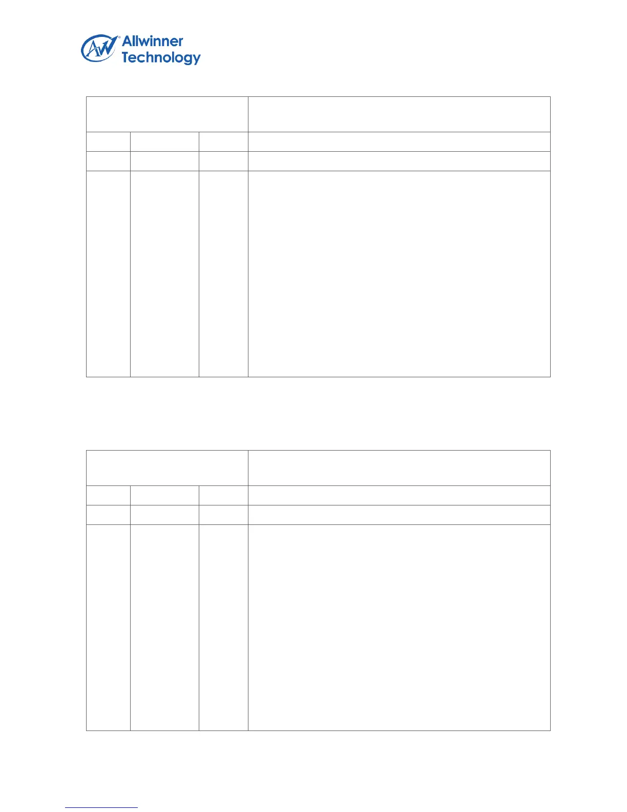
Register Name: UART_DLL
Default Value: 0x0000_0000
DLL
Divisor Latch Low
Lower 8 bits of a 16-bit, read/write, Divisor Latch register that
contains the baud rate divisor for the UART. This register may
only be accessed when the DLAB bit (LCR[7]) is set and the
UART is not busy (USR[0] is zero).
The output baud rate is equal to the serial clock (sclk)
frequency divided by sixteen times the value of the baud rate
divisor, as follows: baud rate = (serial clock freq) / (16 *
divisor).
Note that with the Divisor Latch Registers (DLL and DLH) set
to zero, the baud clock is disabled and no serial
communications occur. Also, once the DLL is set, at least 8
clock cycles of the slowest UART clock should be allowed to
pass before transmitting or receiving data.
6.4.4.4. UART DIVISOR LATCH HIGH REGISTER
Register Name: UART_DLH
Default Value: 0x0000_0000
DLH
Divisor Latch High
Upper 8 bits of a 16-bit, read/write, Divisor Latch register that
contains the baud rate divisor for the UART. This register may
only be accessed when the DLAB bit (LCR[7]) is set and the
UART is not busy (USR[0] is zero).
The output baud rate is equal to the serial clock (sclk)
frequency divided by sixteen times the value of the baud rate
divisor, as follows: baud rate = (serial clock freq) / (16 *
divisor).
Note that with the Divisor Latch Registers (DLL and DLH) set
to zero, the baud clock is disabled and no serial
communications occur. Also, once the DLH is set, at least 8
clock cycles of the slowest UART clock should be allowed to
pass before transmitting or receiving data.
 Loading...