A20 User Manual (Revision 1.2) Copyright © 2013 Allwinner Technology Co., Ltd. All Rights Reserved. Page 624 / 812
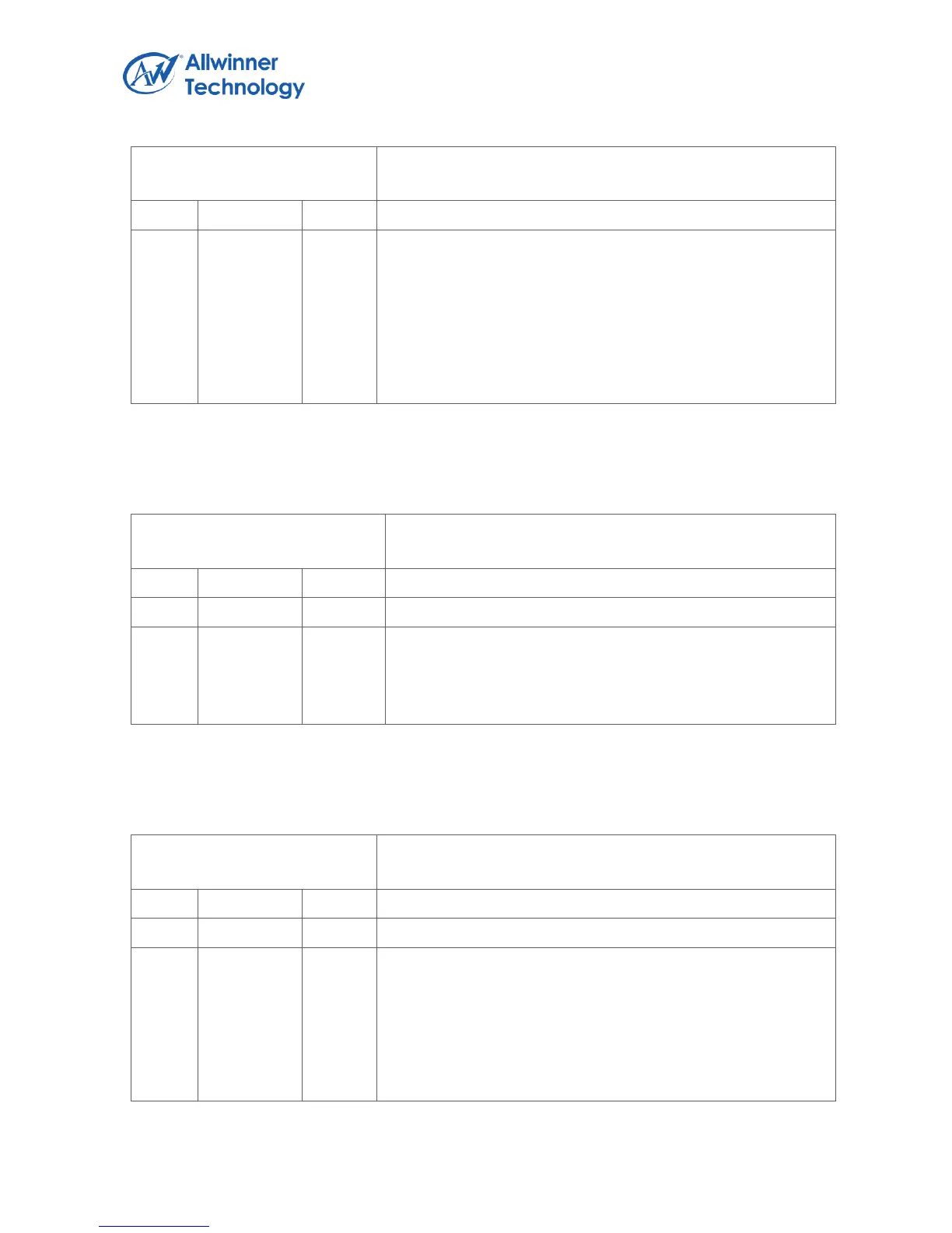
Register Name: UART_MSR
Default Value: 0x0000_0000
0: no change on ctsdsr_n since last read of MSR
1: change on ctsdsr_n since last read of MSR
Reading the MSR clears the DCTS bit. In Loopback Mode
(MCR[4] = 1), DCTS reflects changes on MCR[1] (RTS).
Note: If the DCTS bit is not set and the cts_n signal is asserted
(low) and a reset occurs (software or otherwise), then the
DCTS bit is set when the reset isremoved if the cts_n signal
remains asserted.
6.4.4.12. UART SCRATCH REGISTER
Register Name: UART_SCH
Default Value: 0x0000_0000
SCRATCH_REG
Scratch Register
This register is for programmers to use as a temporary
storage space. It has no defined purpose in the UART.
6.4.4.13. UART STATUS REGISTER
Register Name: UART_USR
Default Value: 0x0000_0006
RFF
Receive FIFO Full
This is used to indicate that the receive FIFO is completely full.
0: Receive FIFO not full
1: Receive FIFO Full
This bit is cleared when the RX FIFO is no longer full.