A20 User Manual (Revision 1.2) Copyright © 2013 Allwinner Technology Co., Ltd. All Rights Reserved. Page 663 / 812
6.8.5.5. EHCI COMPANION PORT ROUTE DESCRIPTION
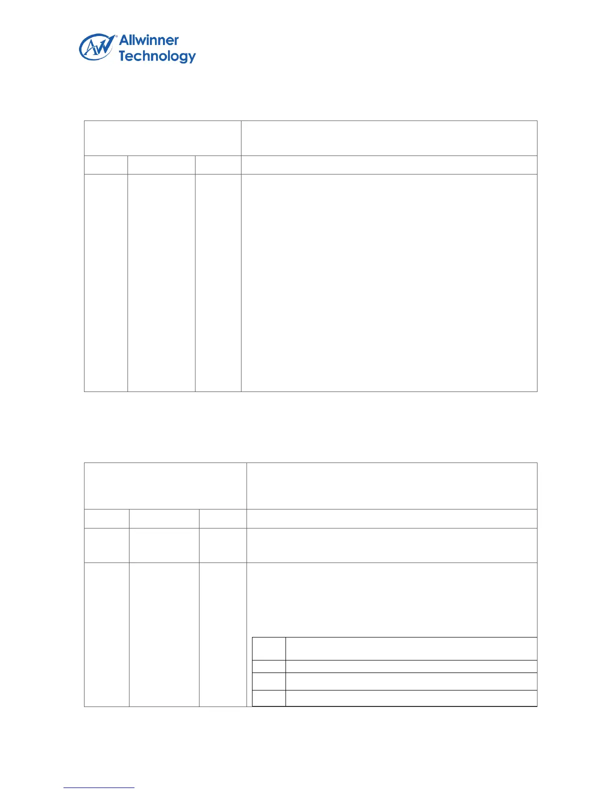
HCSP-PORTROUTE
This optional field is valid only if Port Routing Rules field in
HCSPARAMS register is set to a one.
This field is used to allow a host controller implementation to
explicitly describe to which companion host controller each
implemented port is mapped. This field is a 15-element nibble
array (each 4 bit is one array element). Each array location
corresponds one-to-one with a physical port provided by the
host controller (e.g. PORTROUTE [0] corresponds to the first
PORTSC port, PORTROUTE [1] to the second PORTSC port,
etc.). The value of each element indicates to which of the
companion host controllers this port is routed. Only the first
N_PORTS elements have valid information. A value of zero
indicates that the port is routed to the lowest numbered
function companion host controller. A value of one indicates
that the port is routed to the next lowest numbered function
companion host controller, and so on.
ITC
Interrupt Threshold Control
The value in this field is used by system software to select the
maximum rate at which the host controller will issue
interrupts. The only valid values are defined below: