1-2 | IPS-4 Dual Bench (UV / IR) Analyzer
Calculation Flow
The transmittance measurements contain chemical information that is
used to determine the analyzer output (e.g. concentration of H
2
S). The
following describes the flow of calculations relating transmittance to the
desired analyzer output.
Step 1: Calculate the transmittance at each wavelength (see Equation 1.1).
Step 2: Calculate the absorbance at each wavelength.
A(λ) = -log
10
(T(λ))
Equation 1.2
Step 3: Map the transmittance OR absorbance to an analyte value.
In this step, the factory established calibration converts either transmit-
tance or absorbance information into a value proportional to the analyte
of interest. This calibration will be unique for each application. Because
two Optical Benches are operating in parallel, transmittance information
from one or both of the covered spectral ranges can be used simultane-
ously to model the analyte(s) of interest.
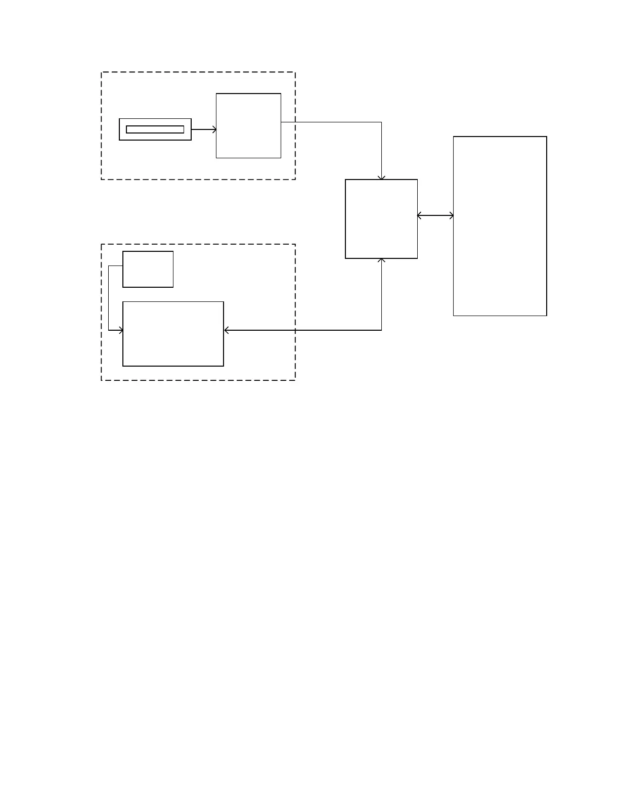
Figure 1-1.
Signal Flow Diagram.
Detector Array
Detector PCB
100-2046
DUVV
Dual-Bench
Interface PCB
403441901
MCU
100-2045
Detector
Preamp
700043901
NDIR Interface PCB
700088901
NDIR