Installation and Start-Up | 3-11
Installing the Optical Bench IR Assembly
After the analyzer has been installed, the Optical Bench Assembly can
be mounted in the Electronics Enclosure. All electrical connections to the
Optical Bench Assembly are made via pre-wired connector plugs (no hard
wiring is required).
Ensure there is no power being supplied to the analyzer while install-
ing the Optical Bench Assembly.
Refer to Figure 3-3b for the locations of the Optical Bench Assembly,
boards, cable connectors, and other components discussed in this
procedure.
!
WARNING
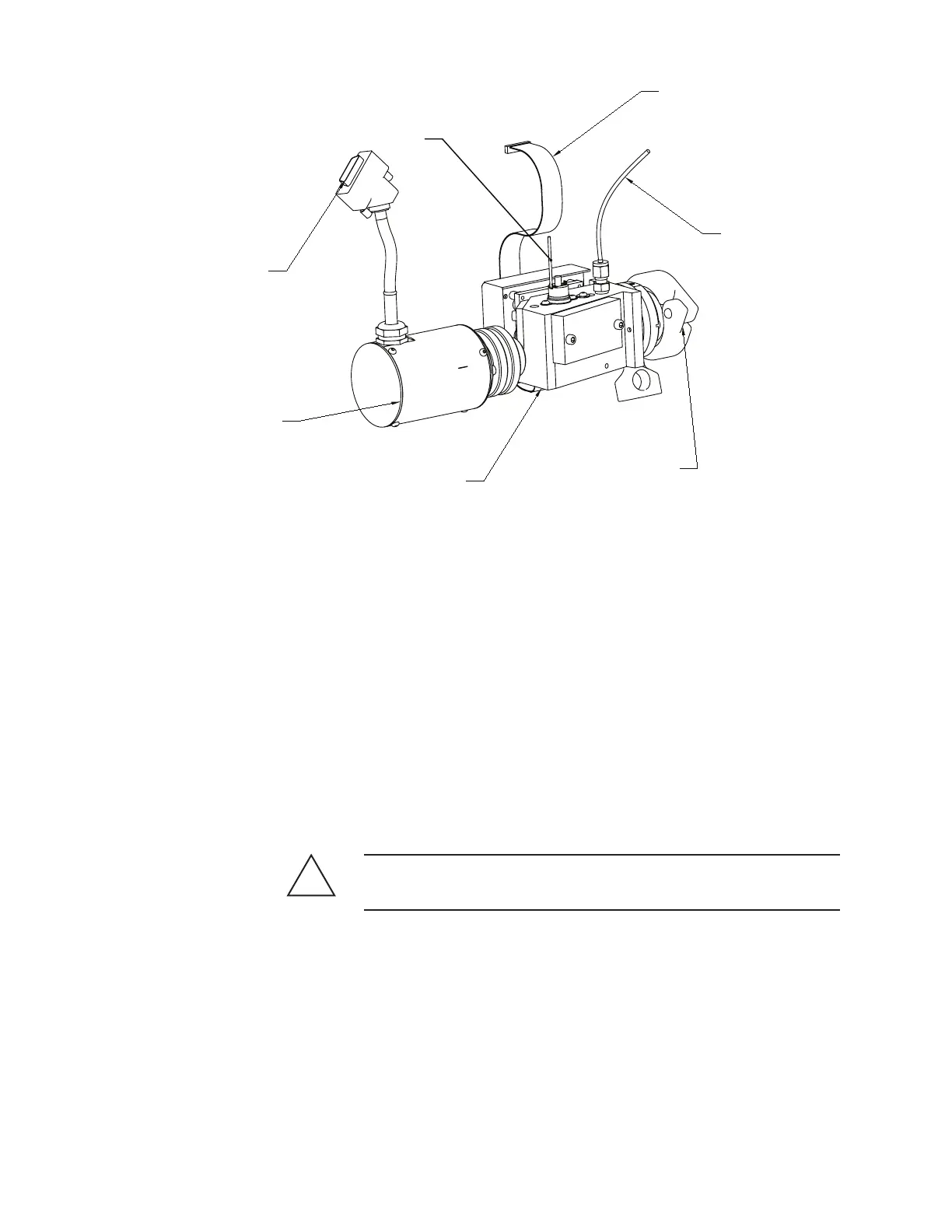
Figure 3-3a.
UV Optical Bench,
Xenon Flash Lamp
Assembly.
NOTE:
DO NOT ADJUST THE ANY COMPONENT ON THE ASSEMBLY,
THE OPTICAL BENCH COMES FACTORY ALIGNED TO THE IT'S
WINDOW HOUSING AND CELL ASSEMBLIES.
CLAMP TO SECURE
OPTICAL BENCH
TO ANALYZER
OPTICAL BENCH
ASSEMBLY
XENON FLASH
LAMB ASSEMBLY
WIRING HARNESSS,
CONNECTS TO
J401B ("BENCH HTR")
ON RELAY BOARD
TO P4 ON DETECTOR INTERFACE
BOARD ON ELECTRONIC
ENCLOSURE DOOR.
RTD CABLE, CONNECTS TO
IN-LINE CONNECTORS
("CON2") LEADING TO
J402 ON ANALOG BOARD
ONNECTOR,
CONNECTS TO J2 ON
XENON LAMP BOARD