3-12 | IPS-4 Dual Bench (UV / IR) Analyzer
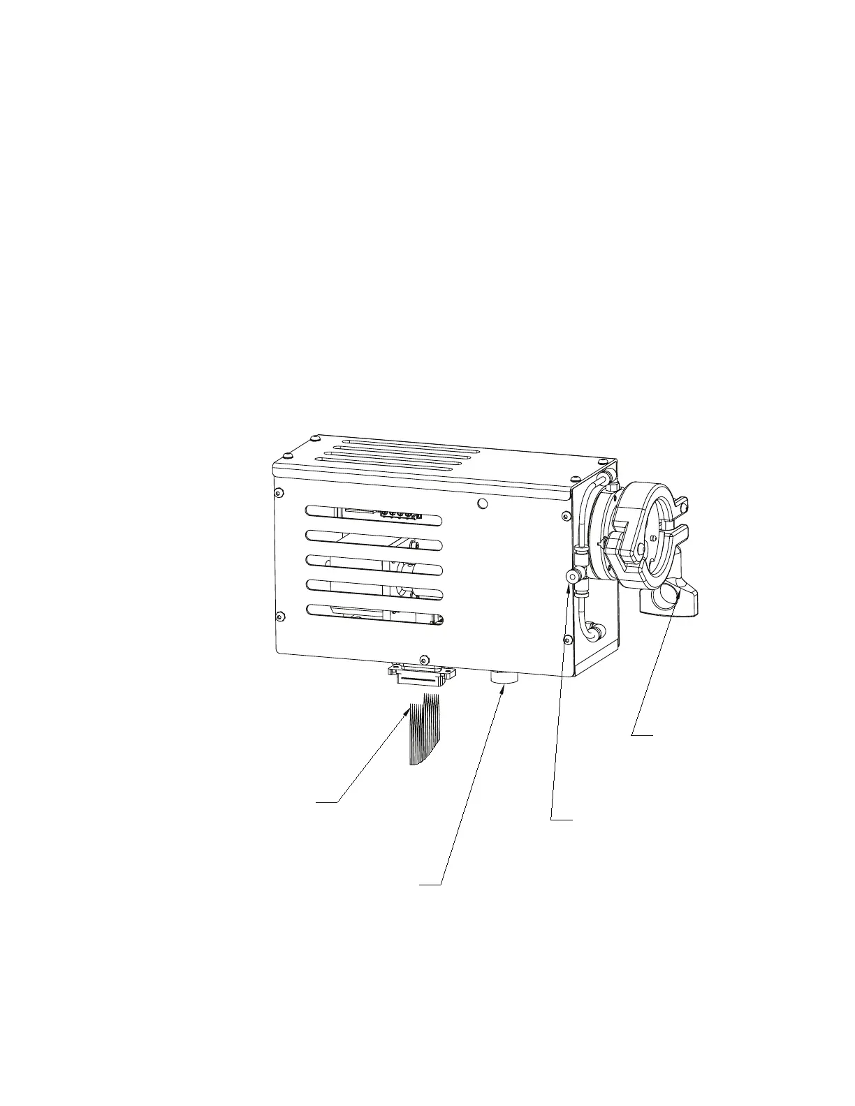
To install the Optical Bench Assembly:
1. Using the locator pins on the NDIR Optical Bench Assembly, position
the Bench Assembly to the lower Window Housing Assembly (Figure
3-3b). Mount the clamp on the interface and secure the assembly in
place.
2. Connect the three pin DC cable connector from DC supply to the mat-
ing connector on the underside of the Optical Bench Assembly.
3. Connect the ribbon cable from the Optical Bench to connector P2 on
the Detector Interface board, mounted to the MCU board.
4. Clamp the ribbon cable using the clamp provided, leaving enough
length on each end to avoid pulling or binding.
5. Connect the purge supply tubing to the purge fitting on the Optical
Bench Assembly.
Figure 3-3b.
IR Optical Bench,
Infrared Source
Assembly.
CLAMP, TO
OPTICAL BENCH
TO ANALYZER
PURGE FITTING
3-PIN FEMALE POWER CONNECTOR,
CONNECTS TO POWER CABLE
FROM DC TERMINAL ASSEMBLY
RIBBON CABLE
CONNECTS TO P2
TECTOR INTERFACE
BOARD