4-26 | IPS-4 Dual Bench (UV / IR) Analyzer
Relay Setup Screens
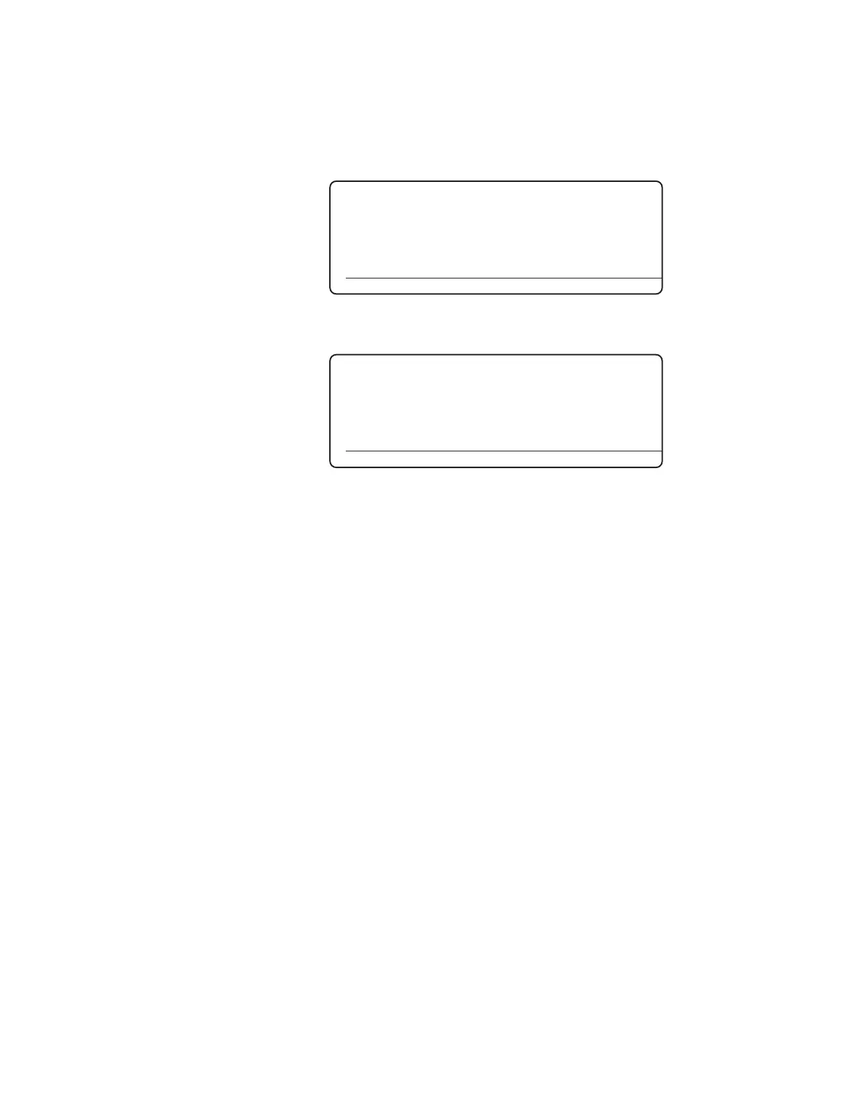
The Relay Setup screens (Figure 4-19a and 4-19b) allow the user to view or
set up the parameters for up to eight relays. For example, Concentration
Alarms can be set up from this screen (Relay Function option).
Figure 4-19a.
Relay Setup screen.
►Relays
Relay 1
Relay 2
Relay 3
Relay 4
Relay 5
HOME ALARMS STATUS SETUP
Figure 4-19b.
Relay Setup screen
(Relay 1).
Relay 1
►Function Disable
Source None
Value 0
Delay 0 Sec N
Normal Oper Normally Open
HOME ALARMS STATUS SETUP
Relay 1–8 Function
The analyzer can use up to eight relays to indicate the operational sta-
tus of the analyzer. Each relay provides one SPST (Form A) dry (poten-
tial free) contact. The relays are energized (closed) on start-up. Relay
Function options include:
Disable
Select Disable to turn off the functionality of a relay.
Calibrating
The relay will be de-energized if the analyzer is in a calibration
state (Span Flush, Span, Zero Flush, or Zero).
Data Valid
The relay will be de-energized when the analyzer is in any state
other than the Measure state.
Fault
The relay will be de-energized if any system fault alarm condition
is triggered within the analyzer diagnostic system. The analyzer
requires service.
The relay will reset automatically upon correction of the fault
alarm.